 EN
EN

Question: Why do 'Adjustable Speed Controllers' (Meter-out vs Meter-in) determine the smoothness of cylinder motion?
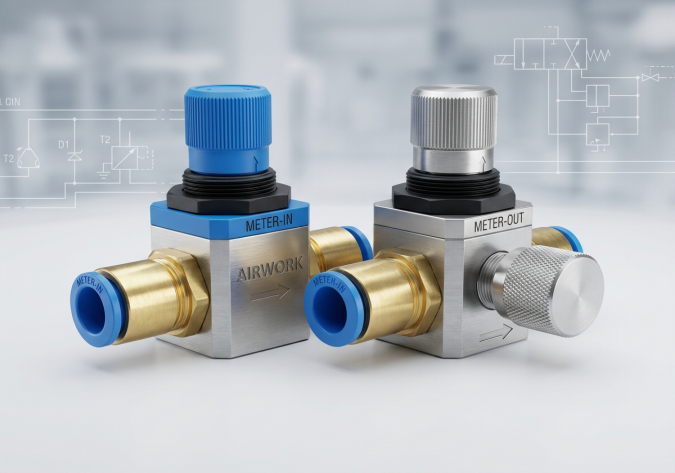
Answer: The smoothness of pneumatic cylinder motion is determined by whether the flow controls are configured for meter-out or meter-in regulation. For double-acting cylinders, meter-out regulation (where the exhausting air is restricted while the supply air enters freely) is the mandatory industry standard. This configuration creates a constant, high-pressure back-pressure cushion in the exhausting chamber that physically sandwiches the piston between two pressurized columns of air. This stable air cushion dampens external load surges, resists gravity, and overcomes high seal breakaway friction smoothly. In contrast, meter-in regulation (where incoming supply air is restricted while exhaust air leaves freely) fails to create any opposing back-pressure. The cylinder piston only moves when the throttled supply pressure slowly builds enough force to overcome static seal friction, causing the cylinder to lurch forward violently in a series of jerky jumps known as the stick-slip effect, which can damage mechanical components and ruin process control.
Introduction: The Challenge of Compressible Fluid Power
Unlike hydraulic systems, which utilize incompressible oil to achieve highly stable and precise speed regulation, pneumatic systems operate on compressed air, which is highly compressible. Because air behaves like a giant spring, controlling the speed and smoothness of a pneumatic cylinder is a significant engineering challenge.
If a cylinder moves erratically, it can cause severe mechanical vibrations, damage delicate parts on a assembly line, cause excessive wear on cylinder seals and guide bearings, and lead to premature component failure. To achieve smooth, controlled linear movement, machine designers must utilize adjustable speed controllers (also known as one-way flow control valves or throttle valves) and apply them in the correct orientation. As a premier supplier of precision pneumatic components, AIRWORK is dedicated to helping B2B systems integrators understand the fluid dynamics behind speed control.
Anatomy of a One-Way Flow Control Valve
To understand how meter-out and meter-in circuits function, it is first necessary to examine the internal construction of a standard adjustable speed controller. A one-way flow control valve consists of two internal elements arranged in parallel inside a single body:
- An Adjustable Needle Valve (Throttle): This is a threaded, tapered needle that can be turned in or out to restrict the size of the air passage, allowing precise regulation of the passing air volume.
- A Non-Return Check Valve (Bypass): This is a flexible elastomer seal or spring-loaded poppet that allows air to flow freely in one direction but blocks all flow in the opposite direction.
Because of this parallel design, the valve behaves differently depending on the direction of the air stream:
- Restrictive Direction: When air enters the valve from the direction that forces the check valve closed, 100% of the air is forced to pass through the narrow needle valve passage. The flow is restricted, and the speed of the air is controlled.
- Free-Flow Direction: When air enters from the opposite direction, the air pressure pushes the check valve open, allowing the bulk of the air to bypass the needle valve and flow through the valve completely unrestricted.
Meter-Out Speed Control: The Industry Standard for Double-Acting Cylinders
In a meter-out configuration, the speed controllers are installed so that they restrict the air leaving the cylinder, while allowing the air entering the cylinder to pass through freely.
- The Working Principle: When compressed air is directed to extend the cylinder, the air enters the rear chamber freely through the check valve of the rear controller, immediately acting against the piston. However, the air in the front chamber (which must be exhausted to allow movement) is blocked by the front controller's check valve. This exhaust air is forced to pass through the front controller's restricted needle valve. As a result, the air escapes slowly, and pressure builds up inside the exhaust chamber.
- Why It Ensures Smoothness: This restricted exhaust creates a constant, stable back-pressure. The piston is effectively clamped between the full supply pressure on one side and a controlled back-pressure on the other. This dual-sided pressure stabilization provides several major advantages:
- Elimination of Stick-Slip: It easily overcomes the high static friction (breakaway friction) of the cylinder seals without a sudden lurch. The moment the piston breaks free, the back-pressure cushion dampens its acceleration.
- Load Compensation: If the external load suddenly drops or shifts (for example, if a vertical cylinder moves a load over a toggle point), the back-pressure cushion prevents the cylinder from accelerating uncontrollably.
- Constant Speed: The cylinder maintains a linear, stable, and predictable speed throughout its entire stroke.
Meter-In Speed Control: When and Why to Avoid It on Double-Acting Cylinders
In a meter-in configuration, the speed controllers are reversed. They restrict the incoming air entering the active chamber, while allowing the exhausting air to leave the opposite chamber freely through the bypass check valves.
- The Working Principle: When air is supplied to extend the cylinder, the exhaust air dumps directly to the atmosphere through the front controller's free-flow path, dropping the exhaust chamber pressure to 0 bar almost instantly. Meanwhile, the supply air slowly creeps into the rear chamber through the restricted needle valve of the rear controller.
- Why It Causes Jerky Motion (Stick-Slip): Because the exhaust chamber is at 0 bar, there is no opposing back-pressure. The piston remains stationary until the pressure in the rear chamber slowly rises high enough to overcome the cylinder's static seal friction and external load. The moment this threshold is reached, the piston leaps forward violently. However, because the piston moves faster than the restricted air can fill the expanding chamber volume, the pressure in the rear chamber drops instantly. The piston halts. The pressure must then slowly build up again until it overcomes friction once more, causing another violent leap. This repeating cycle of leaping and stopping is the classic stick-slip phenomenon.
- Appropriate Applications: Meter-in control is highly problematic for standard double-acting cylinders. However, it is the correct choice for single-acting cylinders (where an internal return spring or gravity provides the necessary opposing force) or for very small micro-bore cylinders (where seal friction is negligible).
Sizing and Installation Best Practices for Systems Integrators
To ensure optimal cylinder smoothness, B2B designers should follow these installation guidelines:
- Mounting Location: Always thread the speed controllers directly into the cylinder ports. Mounting them on the remote directional control valve manifold introduces a large volume of compressible air in the tubing between the cylinder and the controller, which reduces speed sensitivity and control responsiveness.
- Check Arrow Markings: Flow control valves feature printed pneumatic symbols or arrow markings on their bodies. Ensure the arrow pointing towards the free-flow direction matches the supply direction for a meter-out setup.
- Standardize on Fine-Pitch Needles: For precise speed tuning, select speed controllers with fine-pitch adjustment threads. AIRWORK speed controllers are engineered with specialized taper needles and multi-turn dials, allowing maintenance technicians to perform highly granular speed adjustments.
Sourcing Precision Flow Controls from AIRWORK
At AIRWORK, we manufacture a comprehensive range of G-thread and R-thread adjustable speed controllers, including space-saving banjo regulators that mount directly to cylinder end-caps and in-line flow control valves. Our controllers utilize heavy-duty brass housings, high-impact composite knobs, and wear-resistant polyurethane seals to deliver precise, drift-free speed regulation under continuous industrial duty cycles.
By selecting AIRWORK flow controls, systems integrators can ensure maximum cylinder smoothness, eliminate damaging mechanical shocks, and extend the service life of their automation equipment. Visit jzpnu.com to download 3D CAD files, view flow coefficient tables, or consult with our technical support team to optimize your speed control circuits today.
Table of Contents
- Question: Why do 'Adjustable Speed Controllers' (Meter-out vs Meter-in) determine the smoothness of cylinder motion?
- Introduction: The Challenge of Compressible Fluid Power
- Anatomy of a One-Way Flow Control Valve
- Meter-Out Speed Control: The Industry Standard for Double-Acting Cylinders
- Meter-In Speed Control: When and Why to Avoid It on Double-Acting Cylinders
- Sizing and Installation Best Practices for Systems Integrators
- Sourcing Precision Flow Controls from AIRWORK