 EN
EN

Question: How does the engineering of 'Manifold Blocks' reduce leak points and optimize complex 20-valve pneumatic control systems?
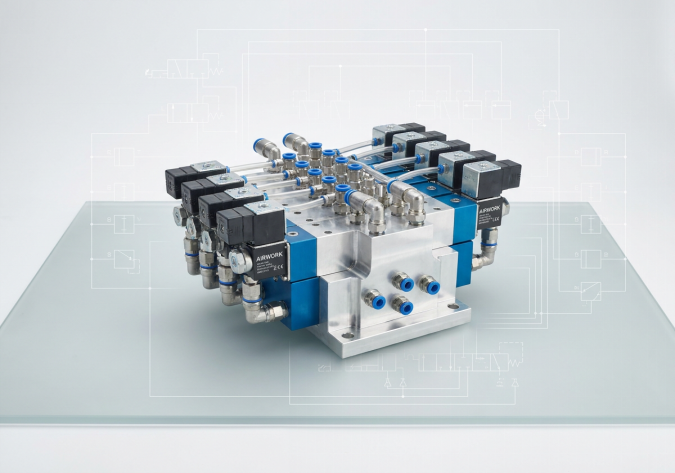
Answer: The engineering of manifold blocks optimizes complex 20-valve pneumatic systems by consolidating individual valve air supplies and exhausts into a single, centralized aluminum sub-base, reducing external leak points by up to 75 percent. In traditional individual valve piping, 20 separate 5/2-way valves would require at least 20 separate supply fittings, 40 exhaust fittings, and dozens of threaded joints and splitters, creating hundreds of potential leakage paths. An engineered manifold block replaces this mess by utilizing shared internal channels for the main pressure supply and dual exhausts. The valves are mounted directly onto the precision-machined face of the manifold block, sealed with high-reliability flat gaskets or O-rings. This reduces external connections down to just one common supply line and two exhaust lines, drastically reducing energy losses, simplifying troubleshooting, and facilitating the integration of smart fieldbus valve terminals.
Introduction: The High Cost of Compressed Air Leaks
In modern industrial plants, compressed air is often referred to as the fourth utility. It is also one of the most expensive. Generating compressed air requires massive electrical energy, and a significant portion of this energy is frequently wasted through system leakage. Industry statistics show that the average manufacturing plant loses 20% to 30% of its compressed air to leaks before it ever reaches an actuator. A single 1-millimeter leak hole in a G1/4 line can cost over one thousand dollars in wasted electricity annually.
In complex automation systems, such as automotive assembly lines, automated sorting machines, or textile looms, it is common to have 20 or more directional control valves operating in close proximity. If these valves are plumbed individually, the sheer number of physical connections makes leakage almost inevitable. As an engineering-focused manufacturer of fluid power controls, AIRWORK designs advanced manifold blocks and valve islands to eliminate these leaks and maximize energy efficiency.
Traditional Individual Piping vs. Engineered Manifolds
To understand the structural advantages of a manifold block, let us compare the physical layout of a 20-valve pneumatic system under two different plumbing methodologies:
- Individual Valve Piping (Plumbing): To plumb 20 separate 5/2-way directional valves, each valve must have its own supply hose connected to its main supply port. Each valve also features two exhaust ports, meaning 40 exhaust hoses and silencers must be managed. This requires a massive web of plastic tubing, hundreds of push-in elbow fittings, and multiple pneumatic distribution blocks or T-connectors. Every threaded fitting represents a potential leak point if it is subjected to vibration or temperature cycling. The physical space required is large, and organizing the lines is a maintenance nightmare.
- Integrated Manifold Block: In an integrated sub-base manifold system, the 20 valves are stripped of their individual supply and exhaust threads. Instead, they feature flat mounting faces with gasket ports on their bottom sides. The manifold block is a single, solid block of hard-anodized aluminum with G1/2 or G3/4 common supply and exhaust channels running through its entire length. The 20 valves are bolted directly to the top face of the block. Flat elastomer gaskets are sandwiched between the valve bodies and the manifold face to form an airtight seal. The only external tubing lines required are the 40 outlet lines running from the manifold directly to the cylinders.
Engineering Principles for High-Station Manifold Blocks
Designing a high-station manifold block (such as a 20-valve assembly) requires careful fluid dynamics calculations to prevent performance degradation:
- Preventing Air Starvation: When many valves on a manifold shift simultaneously, they draw a large volume of air from the common supply channel. If the internal supply channel is too narrow, the pressure inside the manifold will drop rapidly, leading to air starvation. This causes downstream cylinders to move sluggishly or fail to reach their full operating force. To prevent this, AIRWORK engineers common supply channels with generous cross-sectional areas. For 20-station systems, it is also standard practice to pipe the main supply pressure into both ends of the manifold block, ensuring balanced air distribution to all stations.
- Eliminating Exhaust Back-Pressure: Just as air must enter the manifold quickly, the exhausting air must leave immediately. If 20 valves exhaust into a narrow shared channel, back-pressure can build up inside the manifold. This back-pressure can travel back into other non-active valves, causing their spools to shift slowly or causing their cylinders to move unexpectedly. AIRWORK manifolds feature dual, over-sized exhaust channels with high-flow silencers to guarantee rapid, unrestricted depressurization.
- Gasket Sealing Integrity: The sealing face of a manifold block must be machined to extremely tight flatness tolerances (typically within 0.05mm). The mounting screws for each valve must be torqued precisely to prevent uneven gasket compression, which is a common source of micro-leakage. AIRWORK utilizes premium NBR flat gaskets that are resistant to synthetic compressor lubricants and ozone degradation, ensuring a perfect seal for years of operation.
- Modularity and Blanking Plates: Production lines frequently change. A well-engineered manifold block should offer modularity. If you only need 16 valves today but plan to expand to 20 tomorrow, you can install a 20-station manifold block and seal the unused 4 stations with AIRWORK blanking plates. This keeps the system sealed and ready for future upgrades without re-plumbing the entire sub-base.
Smart Integration: From Manifold Blocks to Valve Islands
The ultimate evolution of the manifold block is the pneumatic Valve Island (or Valve Terminal). In a valve island, the mechanical manifold block is merged with a centralized electrical control module. Instead of running 20 individual solenoid cables from a PLC output card to each valve on the manifold, a single multi-pin cable or a digital fieldbus cable (such as EtherCAT, Profinet, or IO-Link) is connected to the valve island's integrated electrical head.
This smart electrical integration provides several major B2B benefits:
- Reduced Wiring Labor: Wiring time is cut from hours to seconds, as only one communication cable and one power cable are needed.
- Advanced Diagnostics: Modern fieldbus valve islands can monitor each solenoid coil for open or short circuits, track valve cycle counts for predictive maintenance, and detect local pressure drops, reporting this data directly to the central PLC.
- Space Savings: The entire electrical and pneumatic control assembly is housed in a compact, clean enclosure, saving cabinet space and reducing machine weight.
Sourcing Precision-Engineered Manifolds from AIRWORK
For systems integrators and OEM machine builders, standardizing on AIRWORK manifold blocks and valve terminals is the key to building high-efficiency, leak-free automation. Our manifolds are machined from premium-grade extruded aluminum, hard-anodized for excellent corrosion resistance, and subjected to 100% leak testing before leaving our factory.
By partnering with AIRWORK, you can reduce your machine assembly times, eliminate expensive air leaks, and deliver a clean, professional-looking control system to your customers. Visit jzpnu.com to download 3D CAD files, view our valve terminal configurators, or speak with our engineering applications team to design your custom pneumatic sub-base today.
Table of Contents
- Question: How does the engineering of 'Manifold Blocks' reduce leak points and optimize complex 20-valve pneumatic control systems?
- Introduction: The High Cost of Compressed Air Leaks
- Traditional Individual Piping vs. Engineered Manifolds
- Engineering Principles for High-Station Manifold Blocks
- Smart Integration: From Manifold Blocks to Valve Islands
- Sourcing Precision-Engineered Manifolds from AIRWORK