 EN
EN

Question: How do you select between 'Shuttle Valves' (OR logic) and 'Dual-Pressure Valves' (AND logic) for pneumatic sequences?
Answer: Selecting between a shuttle valve and a dual-pressure valve depends entirely on the logical requirements of your pneumatic control sequence. Use a shuttle valve when you need OR logic, where a pneumatic output must be generated if pressure is applied to either input A or input B (or both). Inside a shuttle valve, a free-floating ball or spool shifts to seal off the inactive input port, allowing the active signal to pass directly to the output. Conversely, select a dual-pressure valve when you need AND logic, where an output must be generated only when both input A and input B are pressurized simultaneously. Inside a dual-pressure valve, a sliding differential piston blocks the flow until both inlets are pressurized, passing the lower-pressure or later-arriving signal to the output. Standardizing on these passive, purely mechanical logic valves allows automation designers to build explosion-proof, electrical-free, and highly reliable control sub-circuits for industrial machinery.
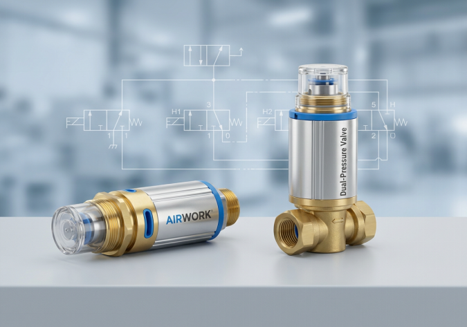
Introduction: The Power of Pure Pneumatic Logic
In the era of programmable logic controllers (PLCs) and digital automation, it is easy to assume that all machine control must be electrical. However, purely pneumatic logic remains an invaluable tool for mechanical designers and systems integrators. Pneumatic logic valves operate without any electrical power, making them inherently safe for explosion-proof zones, paint booths, chemical plants, and high-moisture environments.
Furthermore, incorporating passive logic valves like shuttle valves and dual-pressure valves directly into mechanical manifolds reduces the need for expensive solenoid valves, digital I/O modules, and fieldbus wiring. AIRWORK manufactures a complete range of high-precision brass and aluminum logic valves designed to provide crisp, high-frequency signal routing for complex pneumatic control lines.
Shuttle Valves: Mechanics and B2B Application Cases (OR Logic)
A shuttle valve is essentially a high-speed automatic directional switch. It features two inlet ports (typically labeled X and Y, or 1 and 1) and one outlet port (labeled A, or 2). The internal element is a lightweight ball, a polyurethane shuttle disc, or a sliding spool that moves freely along a cylinder bore.
- The Working Principle: When compressed air enters inlet X, it pushes the shuttle disc toward inlet Y, sealing inlet Y off completely. The air from X then flows freely around the shuttle and exits through outlet A. If air enters inlet Y instead, the shuttle is pushed toward X, sealing X and routing Y to A. If air enters both ports, the port with the higher pressure will seal the opposite port and direct its flow to the outlet.
- Application Case 1 - Remote Manual Override: In large production facilities, operators may need to actuate a critical cylinder (such as a conveyor reject arm or an emergency gate) from two different locations. By installing a shuttle valve near the cylinder, manual push buttons can be run to two separate control panels. Pressing either button will pilot the cylinder through the shuttle valve.
- Application Case 2 - Auxiliary Safety Retraction: A pneumatic clamping fixture can be retracted either by a normal cycle-end valve or by a dedicated manual emergency return valve. A shuttle valve combines these two signal lines to pilot the main directional control valve, ensuring the cylinder can retract under either command.
Dual-Pressure Valves: Mechanics and B2B Application Cases (AND Logic)
While a shuttle valve handles OR operations, a dual-pressure valve is designed for AND logic. It also features two inlet ports (P1 and P2) and one outlet port (A). However, its internal construction is completely different, consisting of a sliding double-seat piston element.
- The Working Principle: If air is applied only to inlet P1, the pressure forces the internal piston to slide toward the opposite side, sealing off outlet A. The same occurs if air is applied only to P2; the piston slides to block outlet A from the other direction. Outlet A will only receive flow when both P1 and P2 are pressurized. When both inlets are active, the piston is balanced, and the signal that arrived last (or the signal with the lower pressure) is allowed to flow past the seats and escape through outlet A.
- Application Case 1 - Mechanical Sequence Interlocks: In automated assembly lines, a secondary cylinder must not extend until the primary clamping cylinder has reached its full extension. An AND logic dual-pressure valve can be used: inlet P1 is connected to the manual cycle start button, and inlet P2 is connected to a mechanical limit valve tripped by the clamp cylinder. The sequence will only initiate if the button is pressed AND the clamp is confirmed fully extended.
- Application Case 2 - Multi-Input Safety Interlocking: On packaging machines with moving safety guards, pneumatic limit valves can be placed on multiple guard doors. By chaining dual-pressure valves together in series, you can create a multi-gate AND interlock. The main pilot pressure to start the machine is only delivered to the start valve when all safety guard limit valves are pressurized, confirming all doors are closed.
Technical Comparison: Making the Right Selection
When selecting between shuttle and dual-pressure valves, automation designers must consider the following technical factors:
- Flow Capacity (Cv or Kv ratings): Shuttle valves are often used to feed pilot lines or even directly power small single-acting cylinders. AIRWORK shuttle valves are engineered with optimized internal flow paths to minimize pressure drop and maintain high Cv ratings. Dual-pressure valves, however, are almost exclusively used for piloting tasks because their internal sliding piston design inherently restricts high flow rates.
- Back-Pressure and Exhaust Dynamics: Shuttle valves can suffer from pilot signal trapping if the exhaust path is not designed correctly. When the active inlet drops to zero pressure, the shuttle must easily shift back to allow the outlet line to exhaust through the control valve. AIRWORK logic valves utilize ultra-low friction polyurethane seals that prevent sticking and ensure rapid exhaust response.
- Sizing and Integration: For compact control cabinets, look for logic valves that can be mounted in-line using threaded air fittings, or look for sub-base manifolds where multiple logic gates are pre-packaged into a single aluminum block to save space.
Sourcing High-Performance Logic Valves from AIRWORK
Whether you are designing a high-speed packaging sequence or an explosion-proof chemical dosing system, AIRWORK is your trusted partner for high-precision logic components. Our shuttle and dual-pressure valves are manufactured from premium anodized aluminum and corrosion-resistant brass, offering excellent sealing performance and a rated service life of over 10 million cycles.
By integrating AIRWORK logic components, systems integrators can ensure maximum system reliability, lower energy consumption, and reduced commissioning times. To download detailed CAD schematics, dimensional drawings, or to get help sizing logic valves for your system, visit jzpnu.com today.
Table of Contents
- Question: How do you select between 'Shuttle Valves' (OR logic) and 'Dual-Pressure Valves' (AND logic) for pneumatic sequences?
- Introduction: The Power of Pure Pneumatic Logic
- Shuttle Valves: Mechanics and B2B Application Cases (OR Logic)
- Dual-Pressure Valves: Mechanics and B2B Application Cases (AND Logic)
- Technical Comparison: Making the Right Selection
- Sourcing High-Performance Logic Valves from AIRWORK