 EN
EN

Question: How to design a 'Two-Hand Safety Control' circuit using dual pneumatic valves for operator protection?
Answer: To design an effective Two-Hand Safety Control pneumatic circuit, engineers must use two separate 3/2-way normally closed manually operated push-button valves connected to a specialized pneumatic two-hand safety control block, which acts as a self-monitoring AND logic device. Under international safety standards like EN 574 and ISO 13851, the circuit must require the operator to press both push-button valves simultaneously within a strict time limit of 0.5 seconds. If only one button is pressed, or if they are pressed sequentially with too much delay, the safety control block must block the pilot air signal and safely exhaust any trapped pressure. This prevents operators from defeating the safety system by tying down or tape-clamping one of the buttons, thereby ensuring that both of the operator's hands are occupied safely away from dangerous pinch points, such as those in pneumatic presses, high-force stamps, or heavy-duty clamping fixtures during the high-pressure working cycle.
Introduction: The Philosophy of Operator Protection in Pneumatics
In modern industrial manufacturing, operator safety is a primary engineering objective. Pneumatic actuators are capable of generating massive forces and rapid movement, which pose a severe risk of crushing or amputation if an operator's hands enter the working area of a machine. Two-hand safety control systems are the standard engineering control utilized to eliminate this risk.
By forcing the operator to use both hands to actuate and maintain the machine cycle, the system physically guarantees that the operator's hands cannot be inside the hazard zone when the machine plunges, clamps, or cuts. As a premier manufacturer of heavy-duty industrial pneumatic components, AIRWORK provides automation designers and system integrators with the reliable valves, safety blocks, and circuit layouts needed to implement robust, compliant, and cost-effective two-hand safety controls.
International Safety Standards and Compliance
When designing a two-hand control system, engineers must comply with recognized international standards, primarily ISO 13851 (which replaced EN 574). These standards categorize two-hand control systems into different types based on their safety integrity level:
- Type I: Requires two manual actuators, but does not enforce simultaneous actuation or anti-defeat monitoring. Not suitable for high-risk machinery.
- Type II: Requires both manual actuators to be released before another cycle can be initiated, but does not enforce simultaneous actuation.
- Type III: The highest safety level. This type requires simultaneous actuation. Both buttons must be pressed within a window of 500 milliseconds (0.5 seconds). If this condition is not met, the system will not actuate. Type III systems are further sub-divided into Type III A, III B, and III C, depending on the redundancy and monitoring capabilities of the pneumatic control elements.
For most dangerous pneumatic applications, such as presses or clamping stations, a Type III safety circuit is the industry-standard mandate. Designing such a system manually using standard logic valves is extremely complex and prone to failure, which is why integrated safety blocks are the preferred solution.
Essential Components of a Dual-Valve Safety Circuit
To build a compliant and reliable Two-Hand Safety Control circuit, you will need the following core AIRWORK components:
- Two 3/2-Way Push-Button Valves: These must be manually operated, spring-return, normally closed (NC) valves. They should be physically separated and shrouded to prevent accidental actuation by a single arm, elbow, or heavy object.
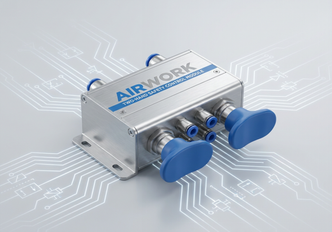
- One AIRWORK Two-Hand Safety Control Block: This is the brain of the safety circuit. It features two input pilot ports and one output signal port. Internally, it contains a specialized sliding piston and diaphragm assembly designed to monitor the pressure rise of both inputs. It will only output a pneumatic pilot signal if both inputs are pressurized within 0.5 seconds of each other.
- One 5/2-Way Double-Pilot Directional Control Valve: This valve controls the main double-acting cylinder. It requires a pilot signal from the safety block to shift into the work stroke position.
- One Double-Acting Pneumatic Cylinder: The actuator performing the high-force work, equipped with appropriate speed controllers and stroke monitoring sensors.
- Emergency Stop and Exhaust Valves: Essential for depressurizing the system in case of power failure or emergency conditions.
Step-by-Step Circuit Design and Operational Logic
Understanding the exact mechanical logic of the two-hand control circuit is vital for system integration. The system operates through four distinct phases:
- Phase 1: The Idle State. In the rest position, both push buttons are released. The inlet air supply is blocked at the push-button valves. The two-hand safety control block has no pressure at its input ports, and its output port is vented to the exhaust. The 5/2-way main control valve remains in the home position, keeping the cylinder rod fully retracted.
- Phase 2: Simultaneous Actuation. The operator presses both push buttons within 0.5 seconds. Compressed air flows from the buttons into the two input ports of the AIRWORK safety control block. Because the pressures arrive almost simultaneously, the internal spool shifts to seal off the exhaust and connects the input air path to the output port. This output pilot signal travels to the pilot port of the 5/2-way main control valve, shifting the spool and extending the pneumatic cylinder to perform the clamp or press operation.
- Phase 3: Delayed or Defeated Press. If the operator attempts to bypass the safety system by tape-clamping or tying down one button, and then presses the second button later, the safety block will detect the timing discrepancy. When the first button is held, pressure enters one input port, shifting the internal safety spool to a locked exhaust position. When the second button is pressed, the air entering the second input port is immediately vented through the block's exhaust. No pilot signal is output, and the cylinder remains safely retracted. To reset the block, both buttons must be fully released.
- Phase 4: Release and Return. Once the work cycle is complete, the operator releases both push buttons. The input air to the safety block is cut off and vented back through the NC push-button exhaust. The safety block output signal drops immediately, allowing the 5/2-way main directional valve to shift back to its default position, which safely retracts the cylinder.
Mechanical Design Best Practices for Systems Integrators
To ensure the safety circuit cannot be bypassed physically, systems integrators should follow these mechanical design rules:
- Physical Distance: According to safety regulations, the two manual push buttons must be mounted at least 260 millimeters apart (center-to-center). This prevents an operator from pressing both buttons using one hand, or using one hand and one elbow of the same arm.
- Protective Shrouds: Each button must be enclosed in a protective shroud or housing. This prevents accidental activation by a falling tool, a passing worker, or the operator leaning their body against the control panel.
- Safe Distance Calculation: The control station must be positioned at a calculated safe distance from the hazard zone. This distance is determined by the stopping time of the pneumatic cylinder. The operator must not be able to release the buttons and reach into the machine before the cylinder has stopped its dangerous movement.
- Heavy-Duty Piping: Use rigid or highly protected tubing between the push buttons and the safety control block to prevent pinching or kinking, which could mimic a continuous pilot signal.
Standardizing on AIRWORK Safety Pneumatics
By sourcing dual pneumatic valves and integrated two-hand safety blocks from AIRWORK, OEM machine builders and industrial distributors can guarantee high-reliability operations. AIRWORK safety valves are engineered with low-friction spools and robust return springs to ensure millions of trouble-free safety cycles, even in harsh manufacturing environments.
For full CAD files, technical data sheets, and custom manifold layouts, visit jzpnu.com or contact our engineering applications group to discuss your specific machine safety requirements today.
Table of Contents
- Question: How to design a 'Two-Hand Safety Control' circuit using dual pneumatic valves for operator protection?
- Introduction: The Philosophy of Operator Protection in Pneumatics
- International Safety Standards and Compliance
- Essential Components of a Dual-Valve Safety Circuit
- Step-by-Step Circuit Design and Operational Logic
- Mechanical Design Best Practices for Systems Integrators
- Standardizing on AIRWORK Safety Pneumatics