 EN
EN

Question: How do you implement 'Soft-Start' (Slow Start) valves to prevent mechanical damage during pneumatic power-up?
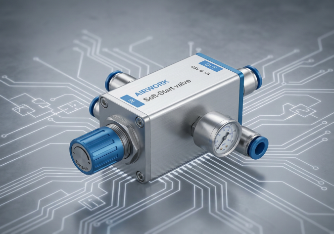
Answer: To implement a soft-start (or slow-start) valve to prevent mechanical damage during pneumatic power-up, engineers must install the valve directly downstream of the main air preparation system (Filter-Regulator-Lubricator, or FRL) and the emergency dump valve, but upstream of the directional control valves. A soft-start valve works on a two-stage pressurization principle: upon initial power-up, it restricts the incoming compressed air flow through an adjustable internal needle valve, allowing system pressure to rise slowly and steadily. This throttled flow causes all unpressurized cylinders to extend or retract gently into their default home positions rather than lurching violently. Once the downstream system pressure reaches a set threshold (typically 50% to 60% of the main supply pressure), the valve's internal pilot piston shifts, opening the main, high-flow bypass port to instantly deliver full system pressure and unrestricted flow capacity. This ensures the machinery can transition smoothly into full, high-speed automated production without suffering high-impact shocks, bent piston rods, or damaged tooling.
Introduction: The Phenomenon of Pneumatic Slam-Start
In industrial automation, systems are frequently shut down for shift changes, maintenance, or emergency situations. During these shutdowns, safety regulations require that all compressed air trapped inside the pneumatic circuits be completely exhausted through dump valves. This leaves all lines and cylinder chambers at atmospheric pressure (0 bar).
When the system is restarted, if full line pressure (typically 6 to 8 bar) is admitted instantly, the air rushes into the empty cylinder chambers at extremely high speed. Because there is no opposing air cushion in the opposite chamber, the cylinder piston accelerates uncontrollably, slamming into the end-cap or striking external mechanical stops. This sudden, violent lurch is known as pneumatic slam-start. It is a major cause of broken sensors, bent piston rods, damaged linear guides, and misaligned tooling, leading to high maintenance costs and unplanned downtime.
Internal Working Principle of a Soft-Start Valve
To prevent slam-start, a soft-start valve utilizes a clever, purely mechanical dual-stage design that splits the pressurization process into two distinct phases:
- Stage 1 - The Throttled Flow Phase: When the main air supply is turned on, the soft-start valve's main high-flow passage is kept closed by a heavy internal spring. The incoming air is forced to pass through a narrow bypass channel containing an adjustable needle valve. This needle valve restricts the flow of air, causing the downstream air pressure in the pneumatic circuit to build up at a slow, controlled rate. As this low-volume air enters the cylinders, they slowly creep into their starting positions.
- Stage 2 - The Full-Flow Phase: The soft-start valve continuously monitors the pressure differential between its inlet and outlet ports. As the downstream pressure rises, it acts against an internal sensing piston. Once this downstream pressure reaches approximately 50% to 60% of the inlet pressure (for example, rising to 3.5 bar on a 6-bar system), the force on the piston overcomes the internal spring tension. The valve's main spool shifts fully open, bypassing the needle valve and establishing a direct, unrestricted high-flow path. The system is now fully pressurized and ready for high-speed operation.
Integration and Placement within the FRL Assembly
For a soft-start valve to function correctly, its placement in the main air preparation assembly is critical. Systems integrators should follow this standard physical layout:
- Filter and Regulator (FRL): The first components in the line must be the water separator, particulate filter, and pressure regulator. These ensure clean, dry air is supplied at a stable pressure.
- Safety Lockout Valve (3/2-way Valve): This manual or electrical valve is used to isolate the system and dump pressure during maintenance or emergencies.
- Soft-Start Valve: The soft-start valve must be placed immediately after the safety lockout valve. If placed before the lockout valve, it will not be able to soften the pressurization of the downstream circuit after a safety dump event.
- Lubricator: If the system requires lubricated air, the lubricator should be placed after the soft-start valve. Placing it before can cause oil pooling inside the soft-start's sensitive pilot passages.
- Valve Manifolds and Cylinders: The outlet of the soft-start valve connects directly to the common supply ports of your directional control valve manifolds.
Step-by-Step Selection and Tuning Guide for Integrators
To maximize the effectiveness of a soft-start valve, it must be sized and adjusted correctly for the specific machine volume:
- Sizing by Flow Rate: Do not size the soft-start valve based on thread size alone. Calculate the maximum simultaneous air consumption of all valves and cylinders operating during peak production. Select a soft-start valve whose Cv rating is equal to or greater than this maximum value to prevent air starvation during normal operation.
- Setting the Ramp-Up Speed: The needle valve on the soft-start is adjustable. Turning the adjustment screw clockwise decreases the starting flow, lengthening the ramp-up time. Turning it counter-clockwise increases flow, shortening the ramp-up time. Adjust the screw so that the cylinders move smoothly at a speed of no more than 50 to 100 millimeters per second during the soft-start phase.
- Verifying the Switchover Point: Watch the main pressure gauge during power-up. Ensure that the cylinders have reached their physical travel limits before the valve clicks open into the full-flow stage. If the valve opens too early, the cylinders will lurch for the remaining portion of their stroke.
B2B Case Study: Protecting High-Speed Packaging Lines
A large-scale food packaging facility was experiencing repeated structural failures on their cartoning machines. Every Monday morning, after the weekend shutdown and safety exhaust, the main air supply was turned on. The sudden pressurization caused the main product pusher cylinder to slam forward, cracking the linear guide blocks and destroying the proximity sensors. This resulted in an average of two hours of weekly downtime and hundreds of dollars in replacement parts.
AIRWORK engineers analyzed the system and recommended installing an integrated FRL assembly equipped with an AIRWORK electric soft-start valve. Upon implementation, the Monday morning start-up sequence became completely silent and smooth. The pushers moved slowly to their home positions, and only after 5 seconds did the system switch to full pressure. Over the next six months, the packaging line reported zero sensor failures and zero mechanical damage, resulting in an immediate return on investment.
Sourcing Premium Air Preparation Components from AIRWORK
At AIRWORK, we manufacture high-reliability, rugged pneumatic components designed to protect your automation assets. Our soft-start valves are built with robust, anodized aluminum bodies and wear-resistant polyurethane seals to withstand millions of cycles in harsh industrial environments. They are available with manual, pneumatic, or electrical pilot overrides to seamlessly integrate with your existing machine safety controllers.
To optimize your pneumatic power-up sequences and eliminate mechanical shock, standardizing on AIRWORK air preparation components is the smart choice. Visit jzpnu.com to download full CAD models, sizing calculators, and installation manuals, or consult with our engineering support team to design your custom FRL manifold today.
Table of Contents
- Question: How do you implement 'Soft-Start' (Slow Start) valves to prevent mechanical damage during pneumatic power-up?
- Introduction: The Phenomenon of Pneumatic Slam-Start
- Internal Working Principle of a Soft-Start Valve
- Integration and Placement within the FRL Assembly
- Step-by-Step Selection and Tuning Guide for Integrators
- B2B Case Study: Protecting High-Speed Packaging Lines
- Sourcing Premium Air Preparation Components from AIRWORK