 EN
EN

Question: How do you design a 'Self-Reciprocating' pneumatic circuit for automated vibration or mixing tasks?
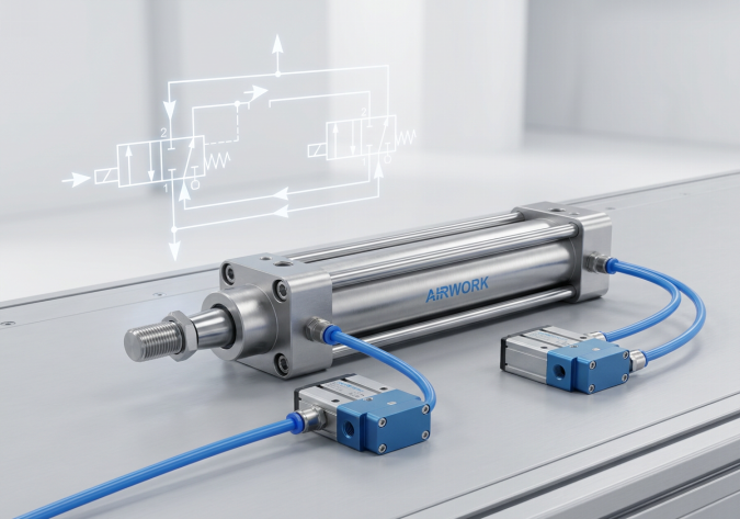
Answer: To design a purely mechanical self-reciprocating pneumatic circuit, engineers must use a 5/2-way double pilot-operated directional control valve as the master power valve, paired with two 3/2-way normally closed roller-lever limit valves mounted at the physical boundaries of the cylinder's stroke. The loop is initiated by routing a start signal through a 3/2-way manual valve. When the start signal is active, the first roller valve, which is mechanically depressed by the retracted piston rod, sends a pilot pressure signal to shift the master 5/2-way valve. This extends the cylinder. When the cylinder reaches full extension, it trips the second roller valve. This valve sends an opposing pilot signal to the other side of the master valve, reversing the flow and retracting the cylinder. When the cylinder returns to its home position, it trips the first roller valve again, restarting the loop. This creates continuous, automatic linear reciprocation without requiring any electronic sensors, PLCs, or electrical wiring.
Introduction: The Advantages of Mechanical Reciprocation
In industrial manufacturing and processing, continuous reciprocating linear motion is a common mechanical requirement. Vibrating sorting screens, chemical mixing vats, powder agitation hoppers, parts washers, and paint stirrers all rely on a constant, repetitive back-and-forth movement to perform their tasks.
While electronic control systems (using PLCs, proximity sensors, and solenoid valves) can easily program this motion, they are not always the best choice. In explosion-proof environments (such as chemical mixing rooms or solvent paint booths), electrical components introduce spark hazards and require expensive explosion-proof enclosures. In high-washdown or dusty zones, delicate electronic sensors can easily fail. A purely pneumatic self-reciprocating circuit is an elegant, highly durable, and inherently safe alternative that runs entirely on compressed air.
Anatomy of a Self-Reciprocating Circuit: Core Components
To build a highly reliable self-reciprocating circuit, systems integrators should utilize these high-performance AIRWORK components:
- One Double-Acting Pneumatic Cylinder: This actuator converts the air pressure into physical reciprocating motion. It should be equipped with adjustable internal end-cushions to absorb the impact forces of continuous reversal.
- One 5/2-Way Double Pilot-Operated Valve (The Master Valve): This valve controls the direction of air flowing to the cylinder. It has no springs; its internal spool remains in its last shifted position until an active pilot signal is applied to the opposite pilot port.
- Two 3/2-Way Roller-Lever Valves (Limit Valves): These NC (normally closed) valves are positioned at the physical limits of the cylinder's stroke (one at 0% extension, and one at 100% extension). They act as pneumatic position sensors.
- One 3/2-Way Manual Toggle or Push-Button Valve (The Start/Stop Valve): This valve acts as the system's main power switch, allowing the operator to start and stop the reciprocating motion.
- Two One-Way Flow Control Valves (Meter-Out Speed Controllers): These are installed directly on the cylinder ports to adjust the extension and retraction speeds, which directly determines the reciprocating frequency.
Circuit Diagram and Step-by-Step Operational Logic
To integrate this circuit, connect the components according to this standard mechanical logic:
- The Starting State (Idle): The start valve is closed. The cylinder piston rod is fully retracted, sitting physically on top of roller-lever valve 1, keeping it depressed (open). The master 5/2-way valve is in its home position, supplying air to the front chamber of the cylinder to hold it in the retracted position.
- Phase 1 - Starting the Loop: The operator switches the 3/2-way start valve to the ON position. Compressed air passes through the start valve, travels through the mechanically depressed (open) roller-lever valve 1, and enters pilot port 14 of the master 5/2-way valve.
- Phase 2 - Extension: The pilot pressure shifts the master 5/2-way valve spool. Air is directed into the cylinder's rear chamber, while air in the front chamber is exhausted. The cylinder rod begins to extend. As soon as the rod moves, it releases roller-lever valve 1, which springs back to its normally closed (exhausting) state. The master valve spool remains in its shifted position due to pilot air trapping.
- Phase 3 - Retraction: As the cylinder rod reaches full extension, it physically strikes and depresses roller-lever valve 2. This opens the valve, allowing compressed air to flow into pilot port 12 of the master valve. The master valve spool shifts back, reversing the air supply. The rear chamber is exhausted, and air is directed into the front chamber, causing the cylinder rod to retract. Roller-lever valve 2 is released and closes.
- Phase 4 - Continuous Re-initiation: The cylinder retracts fully and strikes roller-lever valve 1 again. Air flows back to pilot port 14, shifting the master valve and starting the next extension stroke. This loop repeats indefinitely until the operator turns the start valve to the OFF position, which cuts off the air supply to the roller-lever valves.
Engineering Best Practices: Speed, Frequency, and Durability
To ensure a long, maintenance-free service life for a self-reciprocating system, designers must follow these mechanical guidelines:
- Adjusting Stroke Frequency: The frequency of reciprocation is controlled by adjusting the two one-way flow control valves. Closing the needle valves restricts the exhaust flow, slowing the piston down and lowering the frequency. Opening them increases speed and frequency. Never run the cylinder at maximum speed without cushioning, as the constant hammering will quickly destroy the cylinder end-caps.
- Setting Up Mechanical Cushions: Ensure the pneumatic cylinder features adjustable end-of-stroke cushions. Adjust the cushion needles so that the piston decelerates smoothly just before hitting the end caps, minimizing structural vibrations.
- Proper Roller-Lever Alignment: Mount the roller-lever valves so that the cylinder cam or rod-end striker hits the roller arm at a smooth angle (typically 30 to 45 degrees), rather than direct perpendicular compression. This prevents side-loading and mechanical bending of the valve lever.
- Lubrication and Air Quality: Because a reciprocating system runs continuously, seal wear is high. Ensure the compressed air is properly filtered (5 microns or better) and feed the circuit through an AIRWORK micro-mist lubricator to keep the valve spools and cylinder seals continuously lubricated.
B2B Application: Explosion-Proof Solvent Agitator
A chemical manufacturing plant needed a solution to continuously mix aggressive solvent-based coatings inside a closed vessel. Using electric motors and electronic limit switches was impossible due to the high risk of solvent vapor ignition. The factory was searching for a 100% explosion-proof mixing agitator.
By implementing an AIRWORK self-reciprocating pneumatic circuit, the plant was able to build a rugged, spark-free mixer. A double-acting stainless steel cylinder was connected to a mixing paddle inside the vat. The control system consisted entirely of an AIRWORK 5/2-way double-pilot valve and two G1/8-threaded roller limit valves. The system operated flawlessly at 45 cycles per minute, running 24 hours a day with zero maintenance issues, providing complete spark safety and excellent reliability.
Standardizing on AIRWORK High-Cycle Pneumatics
AIRWORK is committed to delivering heavy-duty, high-precision pneumatic components that perform in the most demanding automation environments. Our directional control valves, roller-lever valves, and ISO-standard cylinders are manufactured with tight tolerances and wear-resistant seals, making them the premier choice for continuous-duty self-reciprocating systems.
By sourcing your components from AIRWORK, you gain access to Italian-engineered quality, comprehensive technical support, and rapid global delivery. To download 3D CAD files, circuit schematics, or to speak with an application engineer about your mixing or vibration project, visit jzpnu.com today.
Table of Contents
- Question: How do you design a 'Self-Reciprocating' pneumatic circuit for automated vibration or mixing tasks?
- Introduction: The Advantages of Mechanical Reciprocation
- Anatomy of a Self-Reciprocating Circuit: Core Components
- Circuit Diagram and Step-by-Step Operational Logic
- Engineering Best Practices: Speed, Frequency, and Durability
- B2B Application: Explosion-Proof Solvent Agitator
- Standardizing on AIRWORK High-Cycle Pneumatics