 EN
EN

Question: How do you select and implement 'Check Valves' for vertical load holding to manage the risks of sudden air pressure loss?
Answer: To hold vertical loads safely and manage the risks of sudden air pressure loss, systems integrators must install pilot-operated check valves (PO checks) directly into the ports of the vertical cylinder. Standard directional control spool valves suffer from microscopic internal clearance leakage, which allows air to escape and causes vertical loads to drift down slowly. More critically, if main supply pressure is lost due to a ruptured hose or compressor failure, a standard circuit will immediately exhaust, causing the heavy vertical load to fall uncontrollably. A pilot-operated check valve prevents this by acting as a zero-leakage mechanical seal. It allows air to enter the cylinder freely, but blocks air from leaving the cylinder port until a positive pneumatic pilot signal is sent to its internal pilot piston. If system pressure drops, the pilot signal is lost, and the check valve instantly snaps shut, locking the compressed air inside the cylinder chamber and holding the load securely in place.
Introduction: The Hazards of Vertical Pneumatic Loads
In industrial automation, vertical axes are highly common. Vertical pneumatic cylinders are widely utilized for lifting heavy components, raising sorting gates, controlling vertical clamping fixtures, and operating packaging indexing heads. However, vertical pneumatic systems present a severe engineering challenge because they must constantly fight the force of gravity.
Unlike horizontal actuators, which simply slide to a halt if pressure is lost, a vertical cylinder carrying a heavy load will drop immediately if the compressed air supporting it is vented. This sudden drop can crush operators, destroy expensive tooling, damage linear guides, and cause massive production scrap. Resolving this hazard requires selecting the correct passive holding components. As an established manufacturer of high-reliability safety pneumatics, AIRWORK provides automation designers with the components and sizing equations needed to implement fail-safe vertical holding circuits.
Why Standard Directional Control Valves are Insufficient
A common mistake among novice automation designers is relying on a standard 5/3-way closed-center solenoid valve to hold a vertical load in place. The logical assumption is that when the valve is in its center (closed) position, all ports are blocked, trapping air in both cylinder chambers and preventing movement. However, this is highly dangerous for two reasons:
- Spool-to-Body Clearance Leakage: Standard 5-port directional control valves utilize a sliding metal-on-metal or soft-sealed spool. To allow the spool to slide back and forth easily, there must be a tiny clearance fit between the spool and the valve bore. Over time, or even in brand-new valves, compressed air slowly bypasses this clearance. This microscopic bypass leakage is enough to cause a vertical cylinder to drift downward by several inches per hour, especially under a heavy load.
- Loss of Mains Pressure: If the main air supply line from the compressor ruptures, or if an emergency stop button is pressed and the main dump valve vents the system, all pressure upstream of the control valve drops to zero. A standard control valve cannot prevent air from escaping back through the ruptured supply hose, resulting in an immediate and violent collapse of the vertical load.
The Mechanics of Pilot-Operated Check Valves (PO Checks)
A pilot-operated check valve is a zero-leakage, seat-type valve that functions as a mechanical block. It features an Inlet port (P), a Cylinder port (A), and a Pilot port (X). Inside the valve, a spring-loaded poppet is pressed firmly against a polished metal seat, creating a perfect, airtight seal.
- Free Flow (Lifting): When air is directed to lift the vertical cylinder, the pressurized air enters inlet port P, overcomes the internal spring tension, lifts the poppet off its seat, and flows freely into cylinder port A to extend the piston and lift the load.
- Blocked Flow (Holding): When the cylinder stops moving, gravity tries to push the piston down, pressurizing port A. This trapped air pressure, combined with the internal valve spring, forces the poppet even tighter against its metal seat. The air is completely locked inside the cylinder chamber, ensuring zero drift.
- Piloted Return (Lowering): To lower the load, compressed air is directed to the opposite side of the cylinder (to push the piston down) and simultaneously directed to the PO check valve's pilot port (X). The pilot pressure pushes an internal piston forward, physically driving a metal pin to push the check poppet off its seat. This opens the exhaust path, allowing the trapped air to escape from port A back through port P, permitting the cylinder to retract smoothly.
Critical Selection Parameters for B2B Systems Integrators
To ensure fail-safe operation, systems integrators must calculate and match the following technical parameters when selecting PO check valves:
- The Pilot Ratio: This is the ratio between the area of the internal pilot piston and the area of the check poppet seat. Common ratios are 3:1, 4:1, and 5:1. For example, in a 3:1 valve, 1 bar of pilot pressure at port X can overcome 3 bar of trapped pressure at cylinder port A. If a vertical cylinder is holding an extremely heavy load, the air pressure inside the lower chamber can rise far above the main line pressure. If the trapped pressure is 9 bar, and your pilot line only delivers 2.5 bar, a 3:1 valve will fail to open, stalling the machine. In high-load applications, engineers must select valves with higher pilot ratios (such as 5:1 or 6:1) or ensure pilot lines have adequate, regulated pressure.
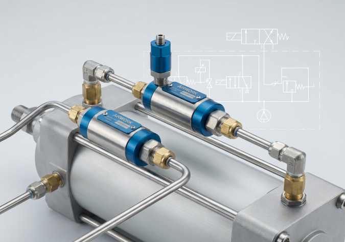
- Direct Port Mounting: To manage the risk of hose rupture, the PO check valve must be threaded directly into the cylinder's port. Never mount the PO check valve on a remote valve manifold with several feet of flexible polyurethane tubing in between. If the tubing between the cylinder and a remotely mounted check valve bursts, the holding circuit is bypassed, and the load will drop immediately. AIRWORK manufactures compact, port-mountable PO check valves that thread directly into cylinder ports, providing maximum safety.
- Thermal Expansion and Overpressure: If a vertical cylinder holds a heavy load in a hot factory environment for extended periods, the trapped air can expand, rising in pressure and exceeding safety ratings. Ensure the system includes safety relief valves if thermal expansion is a risk.
Redundant Safety: Integrating Mechanical Rod Locks
While PO check valves provide excellent protection, they rely on the integrity of the cylinder's internal piston seals. If the cylinder's piston seal wears down or suffers bypass leakage, air will escape from the lower chamber to the upper chamber, causing the load to drift despite the check valves remaining closed.
For safety-critical applications (such as lifters operating directly above assembly workers), safety standards mandate a redundant, mechanical holding system. This is achieved by combining PO check valves with an AIRWORK Mechanical Rod Lock. A rod lock is a spring-engaged, pneumatically released clamping device integrated into the cylinder's front end-cap. When pneumatic pilot pressure is lost, heavy internal springs force a metal collar to clamp tightly around the piston rod, holding it in place with massive physical friction, providing complete mechanical security regardless of air seal integrity.
Sourcing Fail-Safe Solutions from AIRWORK
At AIRWORK, safety is an engineering requirement. Our VB series pilot-operated check valves are manufactured from high-grade anodized aluminum and feature precision-ground brass poppets with high-durability fluorocarbon seals to ensure zero-leakage performance over millions of cycles.
By standardizing on AIRWORK safety check valves and integrated rod lock cylinders, distributors and systems integrators can ensure maximum operator safety and full compliance with machine safety standards. Visit jzpnu.com to download 3D CAD drawings, pilot ratio charts, and safety compliance certificates for your next vertical lifter project.
Table of Contents
- Question: How do you select and implement 'Check Valves' for vertical load holding to manage the risks of sudden air pressure loss?
- Introduction: The Hazards of Vertical Pneumatic Loads
- Why Standard Directional Control Valves are Insufficient
- The Mechanics of Pilot-Operated Check Valves (PO Checks)
- Critical Selection Parameters for B2B Systems Integrators
- Redundant Safety: Integrating Mechanical Rod Locks
- Sourcing Fail-Safe Solutions from AIRWORK