 EN
EN

Q: Troubleshooting Pressure Drops in FRL combinations: Analyzing filter element clogging and regulator sizing.
In an industrial pneumatic system, consistent operating pressure is the lifeblood of automated production lines. When pneumatic actuators begin to sluggishly extend, or when pneumatic clamping tools fail to hold parts securely, the culprit is often a significant pressure drop across the Filter, Regulator, and Lubricator (FRL) combination unit. A pressure drop, or delta P, is the difference in air pressure between the inlet and the outlet of the FRL assembly during dynamic flow conditions.
While a minor pressure drop is mathematically inevitable due to internal friction, excessive pressure drop severely degrades system efficiency. It forces the air compressor to work harder, consuming excessive electrical energy to compensate for the downstream loss. For maintenance engineers and facility managers, troubleshooting these pressure drops requires a systematic analysis of two main factors: filter element clogging and regulator under-sizing. This article provides a comprehensive engineering guide to diagnosing and resolving these dual issues.
The Impact of Pressure Drops on Factory Operations
Many facility managers try to solve downstream speed issues by simply turning up the compressor pressure. This is a highly inefficient and expensive mistake. Every 1 bar increase in compressor output pressure increases the facility's energy costs by approximately 7 percent. Furthermore, over-pressurizing the system accelerates wear on seals, hoses, and pneumatic cylinders, leading to premature failures.
Instead, troubleshooting the FRL combination unit is the correct course of action. When dynamic flow begins, an FRL with high internal resistance will show a sudden, massive drop on its pressure gauge, starving downstream machinery of the flow rate it requires to function at peak speed and torque.
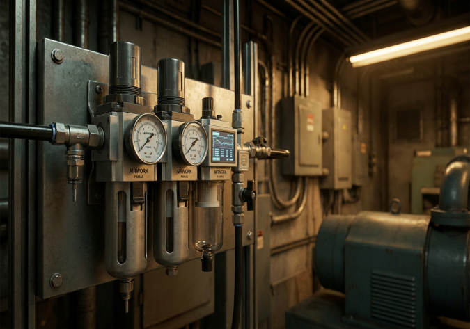
Factor 1: Analyzing Filter Element Clogging
The air filter is the first component in any FRL combination. Its job is to catch rust, scale, and particulates. However, as the filter element performs its job, it inevitably becomes a bottleneck.
The Lifecycle of a Filter Element
Standard pneumatic filters utilize sintered bronze, polyethylene, or fiber elements. These elements feature a porous structure that allows air molecules to pass through while trapping solid contaminants. Over weeks of continuous operation, these trapped contaminants accumulate on the outer surface of the element, forming a filter cake. While this cake can slightly improve filtration efficiency initially, it quickly begins to restrict the open flow area.
How to Diagnose a Clogged Filter Element
To determine if a filter element is clogged without completely dismantling the FRL unit, follow these diagnostic steps:
- Check the Pressure Differential: Install pressure gauges immediately before and after the FRL unit. Measure the pressure under static conditions (no air flowing) and then under dynamic conditions (when the machine is running at full capacity).
- The Delta P Rule: A brand new, clean filter element should exhibit a pressure drop of no more than 0.1 bar to 0.15 bar under normal flow conditions. If the dynamic pressure drop across the filter stage alone exceeds 0.35 bar to 0.5 bar, the element is severely clogged and must be replaced immediately.
- Visual Inspection: Sintered bronze elements will darken from their natural gold/bronze color to a dark brown or black as they fill with solid particulates and oil sludge.
To prevent unexpected clogging, implement a preventive maintenance schedule. Filter elements should be inspected and cleaned (by blowing compressed air from the inside out) every 3 to 6 months, and replaced annually in standard industrial environments.
Factor 2: Regulator Sizing and the Flow Coefficient (Cv)
If the filter element is clean but the pressure drop persists when the machine cycles, the issue is likely rooted in the sizing of the regulator. A common and costly mistake in B2B procurement is purchasing a regulator based solely on the size of the existing pipe threads (e.g., buying a half-inch regulator because the incoming hose is half-inch).
Sizing by Port Size vs. Sizing by Flow Coefficient
Port size is a poor indicator of flow capacity. Two different half-inch regulators can have vastly different internal geometries and flow capacities. To size a regulator correctly, engineers must analyze the Flow Coefficient (Cv) or the rated flow capacity in liters per minute (L/min).
- The Flow Coefficient (Cv) represents the volume of air that can flow through the regulator at a specific pressure drop. A regulator with a low Cv will act as a major restriction when high flow rates are required, causing a severe pressure drop downstream.
- Dynamic vs. Static Pressure: A regulator may show a perfect 6 bar on its gauge when the system is static. However, if the regulator is under-sized, the moment a large cylinder extends, the pressure will plummet because the internal valve orifice cannot pass enough volume fast enough.
Sizing Calculation Checklist for B2B Procurement
To select the correct regulator size for your application, you must define:
- Inlet Pressure: The pressure supplied by the main compressor line.
- Required Outlet Pressure: The specific pressure needed by the machinery.
- Peak Flow Demand: The maximum flow rate required during the machine's heaviest cycle, not just the average flow.
- Allowable Pressure Drop: The maximum acceptable delta P (ideally no more than 0.3 bar across the regulator).
Using the manufacturer's flow curves (such as those provided for the AIRWORK series by JZPNU), locate your required flow on the horizontal axis and your inlet/outlet pressure on the curves. If your peak flow falls into the steep downward slope of the curve, the regulator is too small, and you must select a larger FRL model.
Dynamic Troubleshooting Guide for Maintenance Teams
When a machine exhibits pressure loss, follow this troubleshooting sequence:
- Step 1: Ensure the inlet pressure to the FRL remains stable during machine cycling. If the inlet pressure drops, the issue is upstream (e.g., a restricted main line, too many machines on one branch, or an under-sized compressor).
- Step 2: Clean or replace the filter element in the FRL. This is the most common and cost-effective fix.
- Step 3: Check the regulator's pilot and relief exhaust holes. If they are clogged with dirt or oil, the regulator cannot respond quickly to dynamic flow changes, causing lag and pressure drops.
- Step 4: Verify the lubricator. If the lubricator is over-dribbling oil, the excess oil can travel back into the regulator's self-relieving mechanism, causing internal damage and flow restriction.
Conclusion: Sizing It Right with AIRWORK
At JZPNU, we design our AIRWORK brand modular FRL units with highly optimized internal flow paths. This engineering focus ensures exceptionally high Flow Coefficients relative to their physical footprint, minimizing initial pressure drops. By combining AIRWORK's high-flow regulators with a proactive filter element replacement schedule, maintenance engineers can guarantee constant, stable operating pressure, maximize tool longevity, and significantly lower factory energy consumption.
Table of Contents
- Q: Troubleshooting Pressure Drops in FRL combinations: Analyzing filter element clogging and regulator sizing.
- The Impact of Pressure Drops on Factory Operations
- Factor 1: Analyzing Filter Element Clogging
- Factor 2: Regulator Sizing and the Flow Coefficient (Cv)
- Dynamic Troubleshooting Guide for Maintenance Teams
- Conclusion: Sizing It Right with AIRWORK