 EN
EN

Q: How do you troubleshoot and eliminate 'Pressure Drops' in long pneumatic lines by selecting the correct tubing diameter?
Introduction: The Hidden Drain on Machine Performance
In heavy industrial environments, compressed air must often travel significant distances from the main compressor room and FRL units to individual machines, pneumatic cylinders, and air tools. When these pneumatic lines are long, maintenance managers frequently encounter a frustrating issue: pressure drop. A system that reads a perfect 7.0 bar at the compressor gauge might drop to a sluggish 4.5 bar at the actuator during operation.
Pressure drop represents a direct loss of energy and mechanical force. It causes pneumatic cylinders to move slowly or fail to reach their required torque, and leads to solenoid valves sticking or operating inconsistently. To compensate, factories often turn up the main compressor pressure, which drastically increases electricity bills and accelerates component wear. The real, cost-effective solution lies in understanding fluid dynamics and selecting the correct pneumatic tubing diameter and material.
This guide explains how to calculate, troubleshoot, and eliminate pressure drops in long air lines, ensuring optimal pneumatic performance.
1. The Physics of Pressure Drop in Pneumatic Tubing
Pressure drop in a compressed air line is caused by friction. As air molecules flow through a tube, they rub against the internal walls of the tubing and collide with one another. This friction converts a portion of the kinetic pressure energy into heat energy, which dissipates into the environment. The amount of pressure drop is determined by several physical variables:
- Tubing Length: Pressure drop is directly proportional to length. Doubling the distance of a run doubles the pressure drop, assuming all other factors remain constant.
- Internal Diameter (I.D.): This is the single most critical factor. The resistance to air flow is inversely proportional to the fifth power of the internal diameter. This means that a microscopic increase in internal diameter can result in a massive reduction in pressure drop.
- Flow Rate (Air Velocity): As more compressed air (higher volume in liters per minute or standard cubic feet per minute) is forced through a tube, the velocity of the air increases. High velocity leads to turbulent flow, which exponentially increases friction and pressure drop. Ideally, air velocity in main lines should be kept below 6 to 10 meters per second.
- Internal Surface Roughness: Rougher inner walls create more turbulence and friction. Smooth walls allow for laminar flow, which minimizes pressure loss.
2. The Great Procurement Mistake: O.D. vs. I.D.
A frequent mistake made by procurement managers is purchasing pneumatic tubing based solely on the Outside Diameter (O.D.). In the B2B world, pneumatic fittings are sized by the tubing O.D. (e.g., 6 millimeter, 8 millimeter, 12 millimeter) to ensure a secure physical push-in connection.
However, pneumatic flow capacity is determined entirely by the Inside Diameter (I.D.). Different tubing materials and wall thicknesses have completely different internal dimensions, even if they share the exact same O.D.
- Polyurethane (PU) Tubing (8mm O.D. / 5.5mm I.D.): Highly flexible, excellent for tight bends on moving parts, but has thicker walls, reducing the internal flow area.
- Nylon (PA) Tubing (8mm O.D. / 6.0mm I.D.): Rigid, high-pressure rating, and has thinner walls. This provides a 6.0 millimeter internal diameter, offering significantly more flow area than PU tubing of the same O.D.
Selecting Nylon tubing instead of PU for long straight runs can expand the internal flow area by nearly 20 percent, immediately reducing pressure drop without requiring larger, more expensive fittings.
3. Step-by-Step Troubleshooting for On-Site Pressure Drops
If a machine is suffering from low-force or sluggish pneumatic operation, use this structured diagnostic procedure to locate and resolve the pressure drop:
- Step 1: Perform Static vs. Dynamic Pressure Measurements. Install pressure gauges at two points: immediately after the FRL unit (upstream) and directly at the solenoid valve inlet port (downstream). Read the pressure under static conditions (when the machine is idle) and dynamic conditions (when the cylinder is in motion). If the downstream gauge drops significantly during motion, you have a severe dynamic pressure drop in the supply line.
- Step 2: Evaluate the Equivalent Length of Fittings. Every elbow, tee, and connector in your line acts as a flow restriction. A standard 90-degree elbow fitting can add the equivalent friction of 0.5 to 1.5 meters of straight tubing. If your line is packed with elbow connectors, replace them with straight runs or smooth, sweeping curves in the tubing.
- Step 3: Calculate the Peak Flow Demand. Determine the maximum air consumption of your cylinders during high-speed cycle times. If the peak demand exceeds the flow capacity of your current tubing, the pressure will drop. Use standard flow capacity charts to match your flow requirements with the appropriate internal diameter.
- Step 4: Upgrade the Supply Line Diameter. If a 50-meter run of 8 millimeter O.D. (5.5mm I.D.) PU tubing is causing a 1.5 bar drop, upgrading to 12 millimeter O.D. (9.0mm I.D.) Nylon tubing will cut the pressure drop by more than 80 percent, restoring full pressure and speed to the machine.
- Step 5: Install a Local Air Receiver Tank. For high-draw, intermittent pneumatic loads (such as heavy stamping cylinders), installing a small local air reservoir right next to the machine acts as a physical accumulator. It stores compressed air close to the action, handling the peak inrush flow locally and eliminating the drop across long supply lines.
- Why Choose JZPNU AIRWORK High-Quality Tubing?
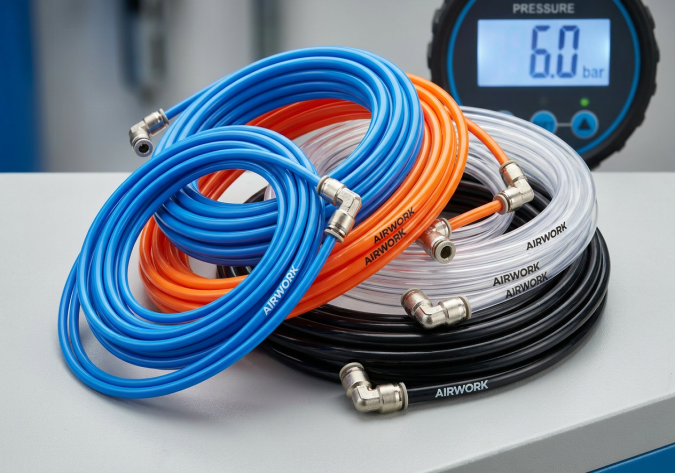
JZPNU (Zhejiang Jinzhi Pneumatic Technology Co., Ltd.) manufactures a comprehensive line of industrial-grade pneumatic tubing under our AIRWORK brand, designed to eliminate pressure drops and maximize system efficiency:
- Ultra-Smooth Internal Walls: Our advanced extrusion lines ensure mirror-finish internal surfaces, reducing the friction coefficient and promoting laminar flow.
- Precise Sizing Tolerances: We maintain incredibly tight tolerances on both O.D. and I.D. (within 0.05 millimeters), ensuring perfect compatibility with push-in fittings and preventing leakage.
- Premium Materials: We source 100 percent virgin polyurethane and nylon resins, providing high pressure ratings, outstanding chemical resistance, and long-term durability without sagging or bursting.
- Complete Sizing Spectrum: We offer tubing in O.D. sizes from 3 millimeter to 16 millimeter, in both metric and imperial configurations, to support any factory layout.
Conclusion: Strategic Sourcing Recommendations
Troubleshooting pressure drops in pneumatic lines is a vital step in maintaining manufacturing productivity and reducing industrial energy waste. Procurement directors and engineering leads should avoid under-sizing air lines to save on immediate hose costs. Instead, partner with a comprehensive manufacturer like JZPNU to specify the optimal tubing diameter and material for your specific layout. By installing high-performance AIRWORK polyurethane and nylon tubing, you protect your pneumatic machinery, lower energy consumption, and guarantee continuous, high-speed automated output.
Table of Contents
- Q: How do you troubleshoot and eliminate 'Pressure Drops' in long pneumatic lines by selecting the correct tubing diameter?
- Introduction: The Hidden Drain on Machine Performance
- 1. The Physics of Pressure Drop in Pneumatic Tubing
- 2. The Great Procurement Mistake: O.D. vs. I.D.
- 3. Step-by-Step Troubleshooting for On-Site Pressure Drops
- Conclusion: Strategic Sourcing Recommendations