 EN
EN

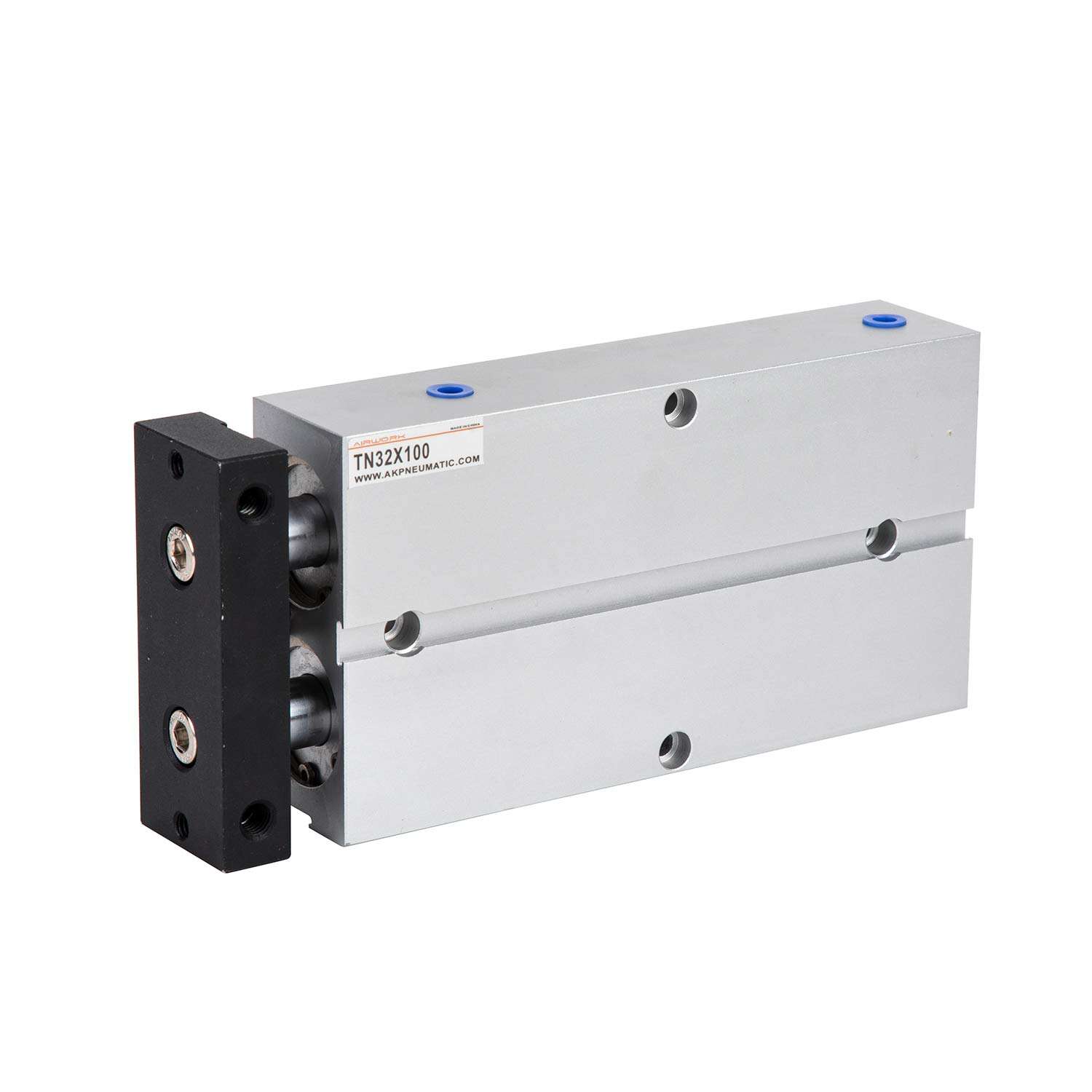
Question: How to synchronize two air cylinders in a parallel lifting system without electronic sensors?
Answer: Achieving perfect synchronization between two pneumatic cylinders in a parallel lifting system without electronic sensors requires replacing simple pneumatic piping with mechanical coupling, hydraulic speed regulators, or precision-balanced pneumatic circuits. Because compressed air is highly compressible, two identical cylinders connected to the same air supply will never extend at the exact same rate if there is even a micro-gram difference in load, frictional resistance, or tubing length. The cylinder with the lighter load or lower friction will always extend first. To resolve this, B2B design engineers must implement rigid mechanical linking (like a torsion bar or guide frame), utilize closed-loop hydro-pneumatic speed control units, or construct symmetric, flow-compensated piping circuits.
Introduction: The Classic Dilemma of Dual Cylinder Lifting
In industrial machine design, lifting or pushing a wide, heavy payload often requires the force of two parallel pneumatic cylinders. For instance, in automated material handling, a dual-cylinder elevator platform might lift heavy wooden crates or metal sheets. If the cylinders do not extend at the exact same speed, the platform will tilt. This tilting causes the payload to slide off, jams the mechanical slide guides, and bends the cylinder piston rods.
While electronic solutions like proportional valves, linear displacement encoders, and PLC closed-loop controllers are highly effective, they are also expensive, complex to program, and vulnerable to electrical interference, high humidity, or explosive atmospheres. For many B2B applications, finding a robust, cost-effective way to synchronize cylinders without electronics is highly desirable. AIRWORK, a top-tier manufacturer of industrial pneumatics, offers several mechanical and fluidic solutions to achieve stable, sensorless synchronization.
Why Pneumatic Cylinders Naturally Run Out of Sync
To engineer a solution, we must first understand why parallel pneumatic cylinders naturally run at different speeds:
- The Path of Least Resistance: Compressed air is a fluid. When air enters a T-junction, it will naturally flow toward the cylinder that requires the least pressure to move. The cylinder with less friction or a slightly lighter load will receive more airflow and move faster.
- Frictional Differences: No two cylinders are identical. Variations in seal pre-load, grease distribution, and guide bush tolerances mean that one cylinder will always have slightly higher breakaway friction than the other.
- Gravity and Off-Center Loads: If a payload is not placed perfectly in the center of the lifting platform, one cylinder will support more weight than the other. The heavily loaded cylinder will require higher pressure to start moving, causing the lightly loaded cylinder to extend first.
Method 1: Stiff Mechanical Coupling (The Simplest and Safest Solution)
If you cannot use electronic sensors, the absolute most reliable way to force synchronization is through rigid mechanical coupling. This method does not try to balance the air pressure; instead, it physically forces the two cylinder rods to move as a single unit.
- Torsion Shaft (Torsion Bar) System: Connect a high-stiffness steel torsion bar across the lifting platform. At each end of the torsion bar, install a gear pinion that meshes with a vertical rack gear fixed to the machine frame. When cylinder A tries to push ahead of cylinder B, the twisting force is transmitted through the torsion bar to cylinder B, forcing it to keep up. This completely prevents tilting.
- Rigid Bridging and Linear Guides: Connect the two piston rods with a thick, heavy-duty structural steel beam or plate. Mount this beam on robust external linear guide rails with recirculating ball bearing blocks. The linear guides absorb any minor tilting forces, preventing side loads from transferring to the cylinder rods. Note that the bridging member must be highly rigid; a thin, flexible plate will simply bend, leading to mechanical binding.
Method 2: Closed-Loop Hydro-Pneumatic Speed Regulators
Unlike air, oil is virtually incompressible. By combining pneumatic power with hydraulic speed regulation, you can achieve incredibly precise, sensorless synchronization.
- How it Works: Install a dual-acting hydraulic speed regulator (also known as a hydro-pneumatic checker or speed control unit) parallel to each pneumatic cylinder. The hydraulic cylinders are filled with oil and connected to each other in a closed loop. As the pneumatic cylinders extend, they push the hydraulic pistons.
- Speed Equalization: Because the oil cannot compress, the speed of the hydraulic cylinders is governed by the oil flow rate. By routing the oil through a single, double-throttled adjustment valve or cross-connecting the hydraulic chambers, the fluid forces both pistons to move at the exact same velocity, regardless of minor variations in air pressure or load distribution.
- AIRWORK Hydro-Check Series: AIRWORK manufactures integrated pneumatic-hydraulic cylinders and external oil speed regulators designed specifically to smooth out pneumatic motion and ensure steady, synchronized speed under fluctuating loads.
Method 3: Precision-Balanced Pneumatic Piping Circuits
If mechanical linking or hydraulic systems are not feasible due to space or weight constraints, you can optimize the pneumatic circuit to minimize synchronization errors. While not 100 percent perfect, this method is highly effective for moderate loads:
- Symmetric Piping (Equal Tubing Lengths): The pressure drop inside a pneumatic hose increases with length. If you connect the control valve to cylinder A with a 1-meter hose and cylinder B with a 2-meter hose, cylinder A will always react faster. Always use a symmetric manifold or T-connector placed exactly halfway between the two cylinders. Ensure the tubing lengths, diameters, and fitting configurations to both cylinders are identical down to the millimeter.
- Dual Meter-Out Flow Control Valves: Never try to control the speed with a single flow control valve at the main supply. Instead, install a high-precision, adjustable flow control valve directly on the exhaust port of every cylinder end cap (configured for meter-out control). Adjust each valve individually to balance the speeds. The stable exhaust backpressure created by meter-out control helps cushion and equalize the movements.
- Pneumatic Flow Divider Valves: For specialized applications, design engineers can use a pressure-compensated pneumatic flow divider valve. This physical valve splits a single incoming airflow into two equal streams, automatically adjusting its internal spool to maintain equal output flow even if the load pressures on the two output lines differ.
Sizing and Engineering Guidelines for B2B Panel Builders
When designing a parallel lifting system, B2B engineers should follow these sizing rules:
- Oversize the Cylinders: Always size the cylinders so that they operate at 50 to 60 percent of their theoretical output force at system pressure. If the cylinders are running close to their maximum capacity, any minor pressure fluctuation will cause one cylinder to stall, causing severe misalignment.
- Use Spherical Rod Joints: If a mechanical link is used, connect the cylinder rods to the lifting plate using spherical rod eyes. This allows for slight angular play, preventing minor synchronization differences from putting destructive side loads on the rod bearings.
Conclusion: Achieve Robust Automation with AIRWORK
Synchronizing parallel pneumatic cylinders without electronic sensors is highly achievable through proper mechanical design, hydraulic speed checkers, or precision-balanced piping. By standardizing on high-quality AIRWORK cylinders and incorporating robust mechanical guides or oil regulators, machine builders can guarantee steady lifting performance while keeping system costs low.
Visit jzpnu.com to download complete CAD models, study detailed circuit diagrams, and order high-end pneumatic parts for your parallel lifting systems today.
Table of Contents
- Question: How to synchronize two air cylinders in a parallel lifting system without electronic sensors?
- Introduction: The Classic Dilemma of Dual Cylinder Lifting
- Why Pneumatic Cylinders Naturally Run Out of Sync
- Method 1: Stiff Mechanical Coupling (The Simplest and Safest Solution)
- Method 2: Closed-Loop Hydro-Pneumatic Speed Regulators
- Method 3: Precision-Balanced Pneumatic Piping Circuits
- Sizing and Engineering Guidelines for B2B Panel Builders
- Conclusion: Achieve Robust Automation with AIRWORK