 EN
EN

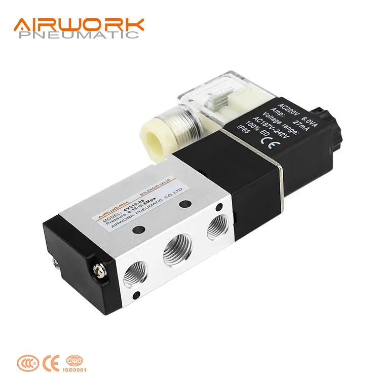
In modern industrial automation, precise control over airflow is fundamental to keeping machinery running safely and efficiently. The air solenoid valve sits at the heart of this control logic, acting as the electromechanical bridge between a controller's signal and the physical movement of compressed air through a pneumatic circuit. Understanding how this component works — and why it behaves the way it does — is essential knowledge for engineers, system integrators, and maintenance professionals who rely on pneumatic automation daily.
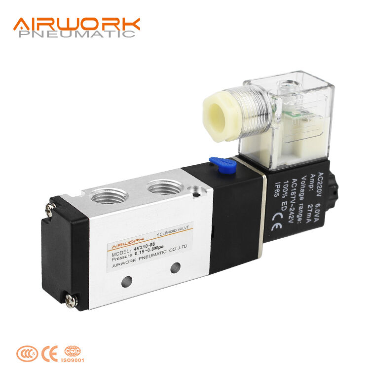
The mechanism behind an air solenoid valve is deceptively simple yet remarkably effective. When an electrical signal energizes the coil inside the valve, a magnetic field is generated that moves a plunger or spool, opening or closing specific air passages within the valve body. This on-demand switching action gives automation systems the ability to sequence actuators, control cylinders, and manage airflow paths with millisecond-level responsiveness. The result is a highly repeatable, low-latency control element that forms the backbone of countless pneumatic automation architectures across industries ranging from automotive assembly to food packaging.
The Internal Mechanism of an Air Solenoid Valve
How the Electromagnetic Coil Drives Valve Movement
At the core of every air solenoid valve is a wound electromagnetic coil wrapped around a ferromagnetic core. When direct current or alternating current is applied to this coil, it generates a concentrated magnetic field. This field exerts a pulling force on a movable armature or plunger that is spring-loaded in its default resting position. The strength of the magnetic pull is precisely engineered to overcome the spring force and shift the plunger into its energized position.
The transition between energized and de-energized states is what creates the switching action that controls airflow. In a direct-acting air solenoid valve, the plunger itself seals or unseals the air passage directly. In pilot-operated designs, the plunger opens a small pilot passage, and the differential air pressure does the work of shifting a larger main spool. This distinction matters significantly when selecting a valve for high-flow or low-pressure applications.
The speed at which a coil can energize and de-energize determines the valve's response time, which is a critical performance parameter in high-cycle automation environments. Industrial-grade coils are designed for millions of switching cycles without degradation, making the air solenoid valve one of the most durable active components in a pneumatic system.
Flow Paths and Port Configurations
The internal geometry of an air solenoid valve defines how many flow paths are available and how they connect when the valve switches states. A 2-way valve has one inlet and one outlet, functioning as a simple on/off gate for airflow. A 3-way valve adds an exhaust port, allowing it to pressurize or exhaust a single actuator port — making it ideal for single-acting cylinders and vacuum applications.
The 5/2-way air solenoid valve configuration is among the most widely used in automation. It has five ports and two switching positions, enabling it to extend and retract a double-acting cylinder by alternately pressurizing and exhausting each side of the cylinder. The 5/3-way configuration adds a third center position, which can be used to hold an actuator in place, exhaust both cylinder ports simultaneously, or pressurize both ports depending on the center condition specified.
Choosing the correct port configuration for an air solenoid valve is not merely a technical specification exercise — it directly determines what kind of motion profiles and safety behaviors the system can achieve. Engineers must match the valve's switching logic to the actuator's requirements and the overall system's fail-safe needs.
How an Air Solenoid Valve Integrates into Automation Control Systems
Signal Interface and Electrical Control
An air solenoid valve receives its operating signal from a control system such as a programmable logic controller, a relay panel, or a dedicated motion controller. The coil voltage rating — typically 24VDC, 110VAC, or 220VAC — must match the output card voltage of the controller. In modern automation, 24VDC solenoids are the dominant standard because they interface directly with PLC output modules without requiring additional signal conditioning.
When the PLC output turns on, current flows through the solenoid coil and the air solenoid valve actuates within its rated response time, typically between 10 and 50 milliseconds for industrial-grade valves. This near-instantaneous response allows the control system to precisely time airflow delivery relative to machine position, sensor feedback, or process conditions. The integration of position sensors and pressure switches further closes the control loop, giving the system real-time awareness of whether the air solenoid valve has performed its intended switching action.
In distributed control architectures, multiple air solenoid valves are often assembled on a common manifold and connected to a fieldbus network such as DeviceNet, Profibus, or EtherNet/IP. This manifold valve island approach reduces wiring complexity dramatically and allows the PLC to address each individual air solenoid valve through a single network connection rather than discrete wiring runs.
Pilot Pressure, Flow Capacity, and System Pressure Range
Every air solenoid valve has a specified operating pressure range within which it will switch reliably. Direct-acting valves can operate at zero differential pressure because the coil force alone moves the plunger. Pilot-operated valves require a minimum pressure differential — typically 0.15 to 0.3 MPa — to actuate the main spool after the pilot stage opens. Selecting a pilot-operated air solenoid valve for a low-pressure system without accounting for this minimum pilot pressure is a common source of field failures.
Flow capacity, expressed as a Cv or Kv coefficient, determines how much air volume the valve can pass at a given pressure differential. Undersizing the air solenoid valve restricts the airflow available to the actuator, resulting in slow cylinder speeds and inadequate clamping or cutting forces. Oversizing adds unnecessary cost and bulk but rarely causes functional problems. The correct sizing approach involves calculating the required flow rate based on the actuator volume and the target cycle time, then selecting a valve with a Cv value that meets or slightly exceeds that requirement.
Pressure ratings also affect the seal integrity of the air solenoid valve. Valves used near the upper limit of their rated pressure experience higher seal stress, which can shorten service life if the seals are not rated for sustained high-pressure operation. This is especially relevant in applications where supply pressure fluctuates and occasionally spikes above nominal levels.
Valve Types and Their Role in Airflow Control Strategies
Single-Solenoid Versus Double-Solenoid Designs
A single-solenoid air solenoid valve uses one coil to shift the valve to its actuated position, with a return spring bringing it back to the default position when the coil is de-energized. This design is inherently fail-safe — when electrical power is lost, the valve reverts to its spring-offset position, which can be configured as normally open or normally closed depending on the application's safety requirements.
A double-solenoid air solenoid valve has two coils, one at each end of the spool. Each coil shifts the spool in one direction, and the spool remains in its last-switched position when both coils are de-energized. This memory function is valuable in applications where the actuator must hold its position during a power interruption, such as a clamping fixture that must not release a workpiece if power is lost mid-cycle.
The choice between single and double solenoid configurations is a safety and process architecture decision as much as a functional one. System designers must analyze failure modes carefully and determine which valve default state creates the least hazardous condition for the machine and operators involved.
Normally Open and Normally Closed Configurations
In a normally closed air solenoid valve, the air passage is blocked in the de-energized state and opens only when the coil is energized. This is the most common configuration for general automation because it prevents unintended actuator movement during startup or power loss. It also conserves energy in applications where the valve spends most of its time in the closed state, since no current is needed to maintain the closed position.
A normally open air solenoid valve passes air freely when de-energized and closes only when the coil is energized. This configuration is appropriate for applications where continuous airflow is the default operating state and interruption of flow represents a control intervention — for example, in cooling circuits or lubrication air systems that must remain active unless specifically commanded to stop.
Understanding the default state behavior of each air solenoid valve in a system is critical during both the design phase and troubleshooting. A technician diagnosing an unexpected actuator movement must know whether the valve in question defaults to open or closed, since this determines how the system behaves during a PLC fault, a blown fuse, or a disconnected cable.
Practical Considerations for Air Solenoid Valve Performance and Longevity
Air Quality and Filtration Requirements
The air solenoid valve is a precision device with tight internal clearances, and the quality of compressed air supplied to it directly affects its service life. Contaminated air containing moisture, oil aerosols, or particulate matter degrades valve seals, causes spool sticking, and accelerates corrosion of internal components. Most air solenoid valve manufacturers specify a maximum particle size — typically 5 to 40 microns — and a maximum pressure dew point for the supply air.
A properly configured FRL unit — filter, regulator, and lubricator — placed upstream of the air solenoid valve protects the valve from the most common contaminants. In systems that use modern polymer seals and self-lubricating spool materials, oil-free air is often preferred, and a lubricator may actually be harmful by washing away the factory-applied grease on internal seals. Always verify the valve manufacturer's recommendation before introducing lubrication into the air supply.
Water contamination is particularly damaging in environments with temperature fluctuations, where moisture condenses inside valve bodies and ports. Installing refrigerated or desiccant dryers upstream of the distribution manifold significantly extends the service intervals for all pneumatic components, including every air solenoid valve in the system.
Coil Temperature, Duty Cycle, and Environmental Ratings
The coil of an air solenoid valve generates heat during operation, and excessive coil temperature is a primary cause of premature coil failure. Continuous-duty coils are wound with wire gauges and insulation classes designed to dissipate heat at rated voltage without exceeding safe operating temperatures. However, operating a coil above its rated voltage — even by a small margin — disproportionately increases heat generation and can shorten coil life significantly.
In high-cycle applications where the air solenoid valve switches hundreds of times per hour, the coil's thermal mass may not be sufficient to prevent heat buildup over a full production shift. In these cases, selecting a valve with an energy-saving circuit that switches from full pull-in voltage to a lower holding voltage after actuation can dramatically reduce coil operating temperature and extend service life.
Environmental protection ratings, expressed as IP ratings, determine where an air solenoid valve can be installed. An IP65-rated valve resists water jets and dust ingress, making it suitable for wash-down environments in food processing or outdoor installations. IP67 and IP68 ratings offer protection against temporary or sustained water immersion. Matching the IP rating of the air solenoid valve to the actual environmental exposure of the installation point prevents premature failure and reduces unplanned downtime.
FAQ
What is the difference between a direct-acting and a pilot-operated air solenoid valve?
A direct-acting air solenoid valve uses the electromagnetic force of the coil to move the valve element directly, which allows it to operate at zero or very low system pressure. A pilot-operated valve uses the coil to open a small pilot passage, then relies on the compressed air's pressure differential to shift the main spool. Pilot-operated valves can handle much higher flow rates for a given coil size, but they require a minimum supply pressure — typically above 0.15 MPa — to function correctly.
How do I select the correct air solenoid valve for a double-acting cylinder?
For a double-acting cylinder, a 5/2-way air solenoid valve is the standard choice. It connects to both the extend and retract ports of the cylinder and routes pressurized air to one side while simultaneously exhausting the other. You also need to calculate the required Cv value based on the cylinder bore, stroke, and desired cycle speed, then select a valve with adequate flow capacity. For applications requiring a mid-stroke hold position, a 5/3-way air solenoid valve with the appropriate center condition should be considered.
Why does an air solenoid valve fail to switch even when the coil is energized?
The most common causes include insufficient supply pressure for pilot-operated designs, a contaminated or sticky spool caused by dirty or wet air, a coil that has failed open-circuit due to overvoltage or overheating, or a voltage mismatch between the coil rating and the control output. Checking supply pressure, verifying coil resistance with a multimeter, and inspecting the air supply quality are the first diagnostic steps. In pilot-operated air solenoid valves, also verify that the minimum operating pressure specified on the datasheet is being met at the valve inlet.
Can an air solenoid valve be used for vacuum applications?
Yes, certain air solenoid valve configurations are suitable for vacuum service. Direct-acting 2-way or 3-way valves are commonly used to apply and release vacuum to suction cups in pick-and-place systems. The key requirement is that the valve's seals and body materials are compatible with the vacuum level being applied, and that the valve is selected for the correct flow direction. Not all air solenoid valves are rated for vacuum — always confirm vacuum compatibility with the manufacturer's datasheet before installation.
Table of Contents
- The Internal Mechanism of an Air Solenoid Valve
- How an Air Solenoid Valve Integrates into Automation Control Systems
- Valve Types and Their Role in Airflow Control Strategies
- Practical Considerations for Air Solenoid Valve Performance and Longevity
-
FAQ
- What is the difference between a direct-acting and a pilot-operated air solenoid valve?
- How do I select the correct air solenoid valve for a double-acting cylinder?
- Why does an air solenoid valve fail to switch even when the coil is energized?
- Can an air solenoid valve be used for vacuum applications?