 EN
EN

Q: The engineering of 'Manifold' systems: Optimizing space and reducing air consumption.
In modern B2B industrial automation, machinery designers are under constant pressure to make equipment more compact, energy-efficient, and cost-effective. Historically, pneumatic systems were built by mounting individual solenoid valves close to their respective cylinders. While simple, this decentralized approach created complex networks of polyurethane tubing, bulky mounting brackets, and massive air pressure losses.
To overcome these inefficiencies, pneumatic engineers utilize valve manifold systems. A pneumatic manifold is a centralized structural block that houses multiple solenoid valves, consolidating air supply, exhaust, and electrical connections into a single compact assembly. Below, we dive into the engineering principles behind pneumatic manifolds, exploring how they optimize physical footprint, reduce air consumption, and improve system performance, along with practical selection criteria from the AIRWORK technical department.
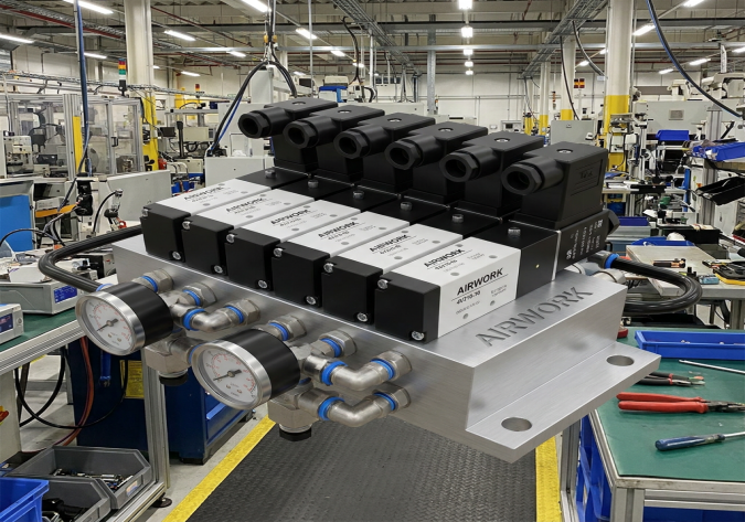
1. Space Optimization: Consolidating the Footprint
The most obvious advantage of a manifold system is physical space reduction. In a traditional decentralized system, each valve requires its own supply line, exhaust port, and mounting hardware. If a machine requires ten valves, that means ten supply hoses, twenty exhaust silencers, and a bird's nest of electrical wiring.
By mounting all ten valves onto a single multi-station manifold block, several engineering advantages are realized:
- Shared Supply and Exhaust Channels: A manifold block features a single, oversized internal gallery for the main air inlet and shared exhaust galleries. Instead of running ten independent supply lines from the FRL unit, you run a single main line. This eliminates dozens of threaded fittings and joint connections, reducing potential leak paths by up to 80 percent.
- Integrated Electrical Connections: Modern manifolds often replace individual solenoid cable leads with a central multi-pin D-sub connector or a digital Fieldbus/Ethernet node. This allows a single cable to transmit control signals to all valves on the manifold, drastically cleaning up the electrical cabinet and reducing assembly time.
- Compact Cabinet Design: Because the valves are closely spaced, they can be housed within a much smaller sub-panel or control cabinet, freeing up valuable floor space on the production machine.
2. Reducing Air Consumption and Dead Volume
Energy efficiency is a key KPI for modern B2B manufacturing plants. Compressed air is one of the most expensive utility inputs in a factory, meaning any reduction in air consumption directly translates to lower operational costs. Manifolds play an essential role in this optimization by minimizing dead volume.
- The Physics of Dead Volume: Dead volume is the volume of air trapped in the pneumatic tubing between the control valve and the cylinder. Every time a valve cycles, this air must be fully pressurized and then fully exhausted to the atmosphere. This air performs zero useful mechanical work; it is purely wasted energy.
- Short-Routing Advantage: By utilizing a centralized manifold positioned strategically close to a cluster of actuators, engineers can run ultra-short working lines to the cylinders. Minimizing the length of these lines reduces the dead volume, which significantly lowers the volume of compressed air consumed during each stroke. In large-scale, high-frequency machines, this simple optimization can save thousands of cubic meters of compressed air annually.
- Common Exhaust Optimization: Consolidating exhausts into a shared gallery allows engineers to route the exhaust air through a single, highly efficient, high-flow silencer. Alternatively, this exhaust air can be captured and routed back into the system to perform low-pressure tasks, a process known as pneumatic energy recovery, which is highly complex to implement with decentralized valves.
3. Flow Dynamics: Sizing the Manifold Properly
Designing a manifold is not just about drilling holes in an aluminum block; it requires careful fluid dynamics analysis. A poorly engineered manifold can starve adjacent valves of air, leading to pressure drops and slow cylinder movements.
- Avoiding Flow Starvation: When multiple valves on a manifold are energized simultaneously, they draw a massive volume of air from the common inlet gallery. If this gallery is undersized, the pressure inside the block will collapse momentarily. This starves the remaining valves, causing sluggish actuator response. AIRWORK manifolds are engineered with oversized internal supply ports to ensure stable, laminar flow across all stations.
- Shared Exhaust Back-Pressure: Similarly, if multiple valves exhaust simultaneously into a shared gallery, back-pressure can build up inside the manifold. If this back-pressure is too high, it can delay the exhaust of adjacent cylinders, causing them to move slowly or shudder. To prevent this, exhaust ports on both ends of the manifold block should be utilized, allowing air to escape from both sides of the assembly.
4. Customization and Modular Flexibility
Industrial machinery is rarely static. Production lines are expanded, and pneumatic logic must be adapted. High-quality manifold systems are designed with modular flexibility in mind:
- Blanking Plates (Station Covers): If a machine is designed for eight valves but initially only requires six, blanking plates can be bolted onto the unused manifold stations. This seals the ports, allowing the system to run while leaving ready-made expansion slots for future pneumatic upgrades.
- Modular Segregation: Advanced manifolds allow engineers to divide the supply gallery into separate pressure zones. For instance, stations 1 to 4 can run on 0.6 MPa for high-force cylinder clamping, while stations 5 to 8 run on a regulated 0.3 MPa for gentle pick-and-place tasks. This multi-pressure capability eliminates the need for separate manifold blocks.
The AIRWORK (JZPNU) Advantage
At Zhejiang Jinzhi Pneumatic Technology Co., Ltd. (JZPNU), we offer highly engineered manifold blocks designed specifically for our 4V series solenoid valves, including the 100M, 200M, 300M, and 400M series.
- Precision Extruded Aluminum: Our manifolds are manufactured from high-tensile, anodized aluminum alloys, ensuring maximum corrosion resistance and flawless sealing surfaces that prevent cross-port air leakage.
- Optimized Flow Pathways: Every AIRWORK manifold block is CNC-machined with mathematically optimized flow galleries, ensuring maximum flow rates (Cv) and zero cross-station starvation, even during high-frequency operation.
- Complete Accessory Ecosystem: We supply everything B2B procurement managers need for a complete assembly, including custom gaskets, high-torque mounting bolts, blanking plates, and specialized high-flow silencers.
By transitioning from decentralized pneumatic layouts to centralized, high-performance AIRWORK manifold systems, you can achieve a cleaner machine layout, faster assembly times, and a significant reduction in compressed air utility costs.
Table of Contents
- Q: The engineering of 'Manifold' systems: Optimizing space and reducing air consumption.
- 1. Space Optimization: Consolidating the Footprint
- 2. Reducing Air Consumption and Dead Volume
- 3. Flow Dynamics: Sizing the Manifold Properly
- 4. Customization and Modular Flexibility
- The AIRWORK (JZPNU) Advantage