 EN
EN

Question: How to calculate the maximum allowable 'Side Load' for DNC series standard cylinders to prevent rod bending?
Answer: Calculating the maximum allowable side load for DNC series ISO 15552 standard cylinders requires evaluating the stroke length, piston rod diameter, operating pressure, and mounting orientation. Side load is any force applied perpendicular to the axis of the piston rod. To calculate the allowable limit, B2B design engineers use physical rod deflection formulas, Euler buckling limits, and manufacturer side-load graphs. Exceeding these limits leads to piston rod deflection, localized cylinder bore wear, and eventual permanent rod bending. To prevent this, engineers must apply external guide units, implement self-aligning rod couplers, or step up to a larger piston rod diameter.
Introduction: The Hidden Threat of Side Loading
In B2B industrial automation, the DNC series standard cylinder is a workhorse, designed to conform to the widely accepted ISO 15552 standard. These tie-rod or profile-groove cylinders are ideal for heavy-duty pushing and pulling tasks. However, in many real-world machine designs, cylinders are incorrectly subjected to lateral or diagonal forces. These are known as side loads.
Pneumatic cylinders are fundamentally designed for axial (straight-line) forces. When lateral forces act on an extended piston rod, they create a bending moment. Without accurate calculations, this bending moment can exceed the yield strength of the steel piston rod, causing permanent deformation (bending) and destroying the internal seals and guide bush. AIRWORK, a top-tier manufacturer of industrial pneumatic components, provides the analytical framework and engineering solutions to prevent these catastrophic failures.
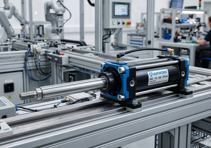
Mechanical Consequences of Excessive Side Load
Understanding what happens inside a DNC series cylinder under side load is crucial for B2B procurement managers and panel builders:
- Rod Bearing Wear: The rod bearing (or guide bush) in the cylinder front cap is designed to guide the piston rod. Side loads press the rod heavily against one side of this bearing, causing rapid wear, friction, and heat generation.
- Piston Seal Off-Centering: As the rod deflects sideways, the internal piston is also forced to tilt. This deforms the piston seal, creating a gap on one side that leads to internal bypass leakage, drift, and pressure loss.
- Cylinder Barrel Scoring: When the piston tilts, the wear ring or the metal body of the piston can make direct contact with the internal aluminum barrel wall, scoring the bore and ruining the cylinder permanently.
- Permanent Rod Bending: If the lateral force exceeds the mechanical elastic limit of the piston rod material (typically carbon steel with hard-chrome plating or stainless steel), the rod will remain permanently bent, locking up the cylinder.
Core Engineering Variables for Side Load Calculations
To perform side load calculations for DNC series cylinders, you must gather four vital parameters:
- Parameter 1: Piston Rod Diameter (d). Common DNC cylinders have standard rod diameters depending on the bore size. For example, a DNC-50 cylinder (50mm bore) typically has a 20mm diameter rod, while a DNC-100 has a 25mm or 32mm rod.
- Parameter 2: Extended Stroke Length (S). The longer the stroke, the greater the lever arm (bending moment) of the side load. Cylinders with stroke lengths exceeding 300mm are highly vulnerable to side load failures.
- Parameter 3: Cylinder Mounting Style. How the cylinder is secured greatly affects its stiffness. A rigid front flange mount resists side load better than a rear clevis pivot mount, which behaves like a hinged beam.
- Parameter 4: Rod Connection Type. Rigid thread connections transmit 100 percent of any misalignment or lateral force directly to the piston rod, while spherical joints or floating joints allow for slight angular deviation, neutralizing bending forces.
Step-by-Step Mathematical Calculation of Deflection and Bending
For a piston rod treated as a cantilever beam (which represents a rigidly mounted cylinder with an extended rod subject to a point side load at the end), we use classical structural mechanics. The standard deflection (y) of a cantilever beam under a point load (F) at its free end is calculated using this formula:
y = (F x L cubed) / (3 x E x I)
Where:
- y is the rod deflection in millimeters.
- F is the lateral side load in Newtons (N).
- L is the unsupported extended length of the rod in millimeters. In practice, this is the stroke length plus the distance from the front cap to the rod end.
- E is the Modulus of Elasticity of the rod material. For standard steel, E is approximately 200,000 Newtons per square millimeter (N/mm squared).
- I is the Area Moment of Inertia of the solid circular piston rod. For a circular cross-section, the formula is:
I = (pi x d to the power of 4) / 64
Where d is the piston rod diameter in millimeters.
Let us calculate the Moment of Inertia (I) for a DNC-50 cylinder with a 20mm piston rod:
- I = (3.14159 x 20 raised to power 4) / 64 = 7,854 mm to the power of 4.
Now, let us assume the cylinder has a stroke length (L) of 300mm and is subjected to a lateral force (F) of 100 Newtons at full extension. We can calculate the expected deflection (y):
- y = (100 N x 300 cubed) / (3 x 200,000 x 7,854)
- y = (100 x 27,000,000) / (4,712,400,000)
- y = 2,700,000,000 / 4,712,400,000 = 0.573 millimeters.
In high-precision automation, a deflection of 0.573mm is extremely dangerous. It is highly likely to cause rapid bearing failure and internal seal leakage. Industry standards recommend keeping the maximum rod deflection under 0.15mm for standard operations. Therefore, for a 300mm stroke, a 100 Newton side load is unacceptable. To solve this, you would need to either reduce the stroke, increase the rod diameter, or install an external guide.
Using Manufacturer Load Diagrams (The Fast B2B Method)
Because performing manual calculations for every design can be time-consuming, AIRWORK provides engineered side-load graphs for our DNC series cylinders. These curves plot the Maximum Allowable Side Load (in Newtons) on the Y-axis against the Extended Stroke Length (in millimeters) on the X-axis for each bore size.
When using these charts, always apply a safety factor of at least 1.5 for static loads and 3.0 for dynamic/impact loads. If your operational parameters lie above the curve for your selected cylinder, you must modify your mechanical design.
Industry-Proven Solutions to Prevent Rod Bending under Side Load
If your mechanical design dictates that lateral forces are unavoidable, use these engineering strategies to protect your DNC cylinders:
- Standardize on Guide Units: AIRWORK offers heavy-duty FENG and HLQ series slide guides that clamp onto the DNC cylinder body. These units feature dual external steel shafts running through linear ball bearings. The external shafts absorb 100 percent of the side load, completely isolating the piston rod from lateral forces.
- Install Self-Aligning Couplers: A self-aligning rod coupler (floating joint) should be threaded onto the piston rod end. This joint allows for angular misalignment of up to 5 degrees and parallel misalignment of up to 2mm. By allowing the connection to pivot, it prevents the transmission of side loads and bending moments to the piston rod.
- Implement Dual-Rod Cylinders: For applications where linear guiding is required but space is limited, choose dual-rod or multi-mount twin-rod cylinders. The double-rod configuration inherently distributes side loads across two points of contact, doubling the resistance to bending.
- Increase Cylinder Bore and Rod Size: If none of the above are feasible, simply oversized the cylinder. Upgrading from a DNC-50 to a DNC-63 increases the piston rod diameter from 20mm to 25mm. Since the Moment of Inertia increases with the fourth power of the diameter, this minor upgrade increases bending resistance by over 140 percent.
Conclusion: Optimize Your Automated Designs with AIRWORK
Accurately calculating and managing side loads is the key to expanding the operating lifespan of DNC series standard cylinders. By selecting high-precision pneumatic parts from AIRWORK and integrating external guides or self-aligning joints, B2B designers can eliminate rod bending failures and reduce maintenance costs.
Explore our interactive CAD configurators and technical side load documentation at jzpnu.com to size your next automation project perfectly.
Table of Contents
- Question: How to calculate the maximum allowable 'Side Load' for DNC series standard cylinders to prevent rod bending?
- Introduction: The Hidden Threat of Side Loading
- Mechanical Consequences of Excessive Side Load
- Core Engineering Variables for Side Load Calculations
- Step-by-Step Mathematical Calculation of Deflection and Bending
- Using Manufacturer Load Diagrams (The Fast B2B Method)
- Industry-Proven Solutions to Prevent Rod Bending under Side Load
- Conclusion: Optimize Your Automated Designs with AIRWORK